


Remote Annex 6300 Hardware Installation Guide
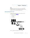
Chapter 1 Introduction
1-6
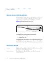
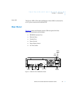
Front Panel Components
Modem Port
Status LEDs
The Remote Annex 6300 has two status LEDs for each modem port
(up to 32, if installed). The status LEDs display modem port status
during system operation.
Table 1-1 describes the modem port status
LEDs.
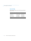
Table 1-1. Modem Port Status LEDs
Modem Config
Status LEDs
The Modem Config Status LEDs indicate the number of modems
installed. An LED is green if all the modems in its group are good. An
LED is amber if one or more modems in its group are bad.
PRI Channel
Status LEDs
The PRI Channel Status LEDs indicate B channel allocation. There are
32 PRI Channel Status LEDs on the front of the Remote Annex 6300.
For T1, 23 are used to indicate B channel allocation. For E1, 30 are used
for B channel allocation.
LED Description
CD CD (Data Carrier Detect) LED is green and ON when carrier has
been detected by the corresponding modem. There are 32 CD
LEDs, one LED per channel, on the front of the Remote Annex
6300.
TX/RX TX/RX LED is green and flashes to indicate the corresponding
modem is transmitting or receiving data. There are 32 TX/RX
LEDs, one LED per channel, on the front of the Remote Annex
6300. For North American models, up to 32 modems can be
installed (although only 23 are active at any given time). For
European countries that use E1 lines for PRI access, a maximum
of 32 modems can be installed (only 30 are active at any given
time).