


4-1Remote Annex 6300 Hardware Installation Guide
Chapter 4 Troubleshooting Procedures
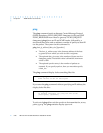
The Remote Annex 6300’s front panel contains a number of LEDs
that provide information about normal operations and about
problems that occur. Use these LEDs and the ROM Monitor
commands to diagnose problems.
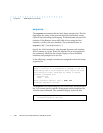
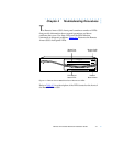
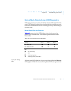
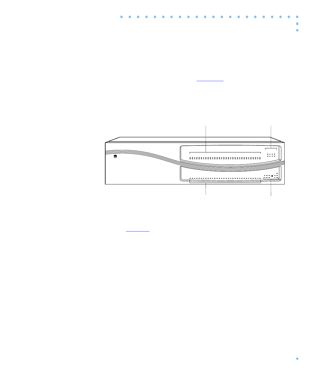
Figure 4-1 illustrates the Remote
Annex 6300’s front panel LEDs.
Figure 4-1. Remote Annex 6300 Front Panel Alarms and LEDs
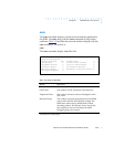
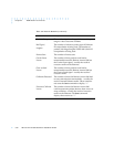
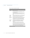
Refer to Table 4-1 for a description of the LEDs located on the front of
the Remote Annex 6300.
Network
Status Alarms
Bay Networks
Remote Annex 6300
Xylogics,
a Bay Networks Company
32 31 30 29 28 27 26 25 24 23 22 21 20 19 18 17 16 15
Modem Status
1413121110987654321
CD
Tx/Rx
13-16 9-12 5-8 1-4
29-3225-2821-2417-20
Modem Config
Status
Test SyncLos
Red Yel Blu
Stat Traf
Setup
Reset
Power
Attn
Network/Status
Ararms
3231302928272625242322212019181716151413121110987654321
PRI Channel Status
Modem Config
Status LEDs
Modem Port
Status LEDs
PRI Channel
Status LEDs