


Remote Annex 6300 Hardware Installation Guide
Chapter 4 Troubleshooting Procedures
4-4
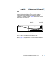
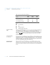
In addition to the front panel LEDs, the Remote Annex 6300 contains
a Link LED on the rear panel. The Link LED is green when an active
10BaseT segment is attached.
During power-up and booting, it is more difficult to diagnose
problems because they can originate in the Remote Annex 6300, the
transceiver, the Ethernet, or the load server host. However, the LEDs
provide both a progress report and an error display to assist you in
troubleshooting.
If an error occurs, save the status of these LEDs. Technical
support personnel can use this information to
diagnose problems.
This chapter describes power-up and booting, troubleshooting
during booting, and the file created from a Remote Annex 6300 dump.
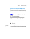
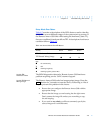
Power-up and Boot Procedures
The Remote Annex 6300 has two modes of operation: normal and
setup. Normal mode is the standard operational mode. Setup mode
provides access to the ROM Monitor commands. Pressing the
button on the front panel puts the Remote Annex 6300 into Setup
mode. When the Remote Annex 6300 is in Setup mode, the Setup LED
lights.
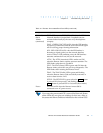
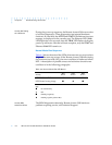
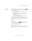
During the Remote Annex 6300 power-up and boot sequence, the
Remote Annex 6300 runs a set of diagnostics. The system LEDs
display the diagnostics’ status. The Remote Annex 6300 stops when
it detects one of two error conditions (see Table 4-2). The pattern of
the system LEDs identifies the error condition.
Reset