


Remote Annex 6300 Hardware Installation Guide
Chapter 2 Installing the Remote Annex 6300
2-16
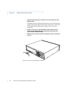
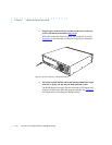
If the ATTN LED is ON or flashing, one of the following failures
has occurred (see Chapter 4 for more details):
❑ Remote Annex hardware failure; contact technical
support.
❑ Network or network interface failure; error message
displays on the console.
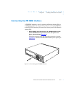
If a network or network interface failure occurs, typing
q accesses the ROM Monitor prompt. Check the network
connection and then see net on page 3-23.
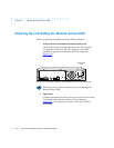
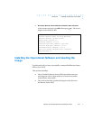
3 Verify the Remote Annex 6300’s hardware configuration.
At the monitor prompt on the console, type config and press
. The screen display looks similar to this:
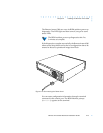
This display is typical for T1 versions. For E1,
information, 32 ports will be shown. For versions
without modems, no port or modem information
will be shown.
Retur
n
REVISION/CONFIGURATION INFORMATION
ROM Software Rev: 1002
Board ID: 63 Board Type: RA6300
CPU Type: 486DX2 Ethernet Address: 00-80-2D-02-CE-A9
Memory size: 8 Meg EEPROM size: 65504
Flash size: 2 Meg Flash ID: 8989
Available Interfaces (* = selected) ThickNet ThinNet *Twisted Pair
SLC Local DRAM Size: 4 Meg SLC SRAM Size: 128K
TDM Interface: PRI T1 USA Revision: VERSION A MGR=1.117
Modem Country Code: 63
Port # 1 2 3 4 5 6 7 8 9 10 11 12
Modem ID 2883 2883 2883 2883 2883 2883 2883 2883 2883 2883 2883 2883
Mod Status OK OK OK OK OK OK OK OK OK OK OK OK
Port # 13 14 15 16 17 18 19 20 21 22 23 24
Mod ID 2883 2883 2883 2883 2883 2883 2883 2883 2883 2883 2883 2883
Mod Status OK OK OK OK OK OK OK OK OK OK OK OK