


1-3Remote Annex 6300 Hardware Installation Guide
Chapter 1 Introduction
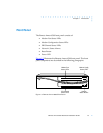
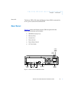
PRI Interface
This interface resides on the MLB in the form of a module whose RJ45
connector is accessible through the rear panel of the Remote Annex
6300. This interface is controlled by a second 486DX2 processor, whch
also controls the internal modems.
Memory
The MLB has 8 megabytes of main DRAM, and an additional 4
megabytes of DRAM is used by the PRI interface controller.
Flash Memory
The MLB supports 2 megabytes of Flash memory.
Modem Carrier Card
Modems
The Remote Annex 6300 can be configured with 0, 4, 8, 12, 16, 24, or
32 internal V.34 modems. The modems, located on quad modem
cards, are installed on the Modem Carrier Card. The modems receive
data from a TTL serial channel and convert the data to a modulated
analog waveform. The analog signal is then presented to a pulse-code-
modulated coder/decoder (PCM codec).
PCM Codec
The Remote Annex 6300 uses PCM codecs to convert the analog
signals coming from the modems into 8-bit serial data streams. The
data streams are multiplexed and passed to the PRI interface along
with data that is purely digital in nature, such as that used with V.120
and synchronous PPP protocols.
Firmware and Software
Firmware
The Remote Annex 6300’s ROM contains firmware for performing
power-up self-tests and loading operational code. A non-volatile
EEPROM stores the configuration parameters.
The Remote Annex 6300 can have a boot image in Flash ROM or can
receive its image from a device on the network; this image is used to
boot the Remote Annex 6300.