


67 - 165 IP Telephony v1.0 Lab 4.1.4 Copyright © 2005, Cisco Systems, Inc.
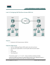
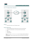
Step 1 Configure the Serial Interface
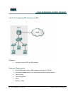
a. In this lab, Pod 1 and Pod 2 will partner, and Pod 3 and Pod 4 will partner.
b. Ensure that a serial cable connects from the lowest serial interface on the lowest pod number
router terminating on the other pod’s lowest number router serial interface.
c. On both pods, use the show ip interface brief command to verify that (1) a serial interface is
installed and (2) the lowest numbered serial interface.
d. What is the port/slot number assigned to the lowest numbered serial interface? ____________
e. On both pods, use the show controllers serial mod/port for the lowest serial interface and
verify if the cable is a DCE or DTE. Examples of this command are show controllers serial 0/0
or show controllers serial 0/1/0.
CMERouterX# show controllers serial mod/port
f. Type the interface serial mod/port command from global configuration mode to access the
serial interface. Examples of this command are interface serial 0/0 or interface serial 0/1/0.
CMERouterX(config)# interface serial mod/port
g. If the pod has the DCE end of the cable, use the command clock rate 115200 to set the clock
rate of the lowest serial interface.
CMERouterX(config-if)# clock rate 64000
h. Use the encapsulation hdlc command to configure the serial link encapsulation to HDLC.
CMERouterX(config-if)# encapsulation hdlc
i. Refer to Table 1 for the appropriate IP address to apply to the serial interface.
CMERouterX(config-if)# ip address 10.X.0.X 255.255.255.0
j. Use the command no shutdown to enable the serial interface.
CMERouterX(config-if)# no shutdown
k. Wait for your partner pod to complete the previous steps. Verify connectivity by using ping to test
the serial connection. Ping the address of your partner pod serial interface. Enter ping 10.Y.0.X
(refer to Table 1 for the partner pod IP address).
l. From an IP phone connected to the pod, attempt to dial a four digit extension numbers of one of
the partner pod IP phones.
m. What was the result, and why is this result? _______________________________________
_____________________________________________________________________________
_____________________________________________________________________________
_____________________________________________________________________________
n. What message displayed on the IP phone when the call did not complete? _________________
Step 2 Configure the Dial Peer
a. From global configuration mode, create a new dial peer with the command dial-peer voice 6
voip.
CMERouterX(config)# dial-peer voice 6 voip