


139 - 165 IP Telephony v1.0 SBA Version 1: Copyright © 2005, Cisco Systems, Inc.
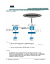
R1 has IP Phones under it to and must be able to forward the calls from these IP Phones to
R2’s IP Phones.
R2 must be able to forward calls to POTS/PSTN and calls to R1’s IP Phones as well.
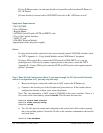
Equipment Requirements
2 2811/2621XM;
2 Cisco IP Phones;
1 Regular Phone;
1 ADTRAN Atlas550 with a PSTN and PRI/T1 card;
2 Cisco Vlan Capable Switches;
1 1MFT-T1 card
1 NM-HDV Network Module;
Appropriated cables and power supplies,
Notes:
- If using switch modules connected to the routers instead external 3550/3560 switches, check
the “IPTX Appendix A - Using Switch Modules on the CME Routers” document.
- If using a FXO card on R1 to connect the PSTN instead a ISDN-PRI/T1 or a you are
planning to use a FXS card to connect regular phones to the routers, check the “IPTX
Appendix B - Using a FXO card to reach the PSTN and FXS card to reach regular internal
phones” document.
Step 1 Basic Switch Configuration (Note: If you went through the CS1 lab and still have the
switch’s configuration on it, you may skip this step)
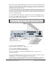
f. Based on the figure, connect the cables but do NOT connect the IP Phones yet.
g. Connect to the console port of the Switches and power them on. If the switches have a
configuration already on them, erase it and reload them.
Note: The vlan information is NOT stored on NVRAM on the newer switches. There is a
file, stored on the flash memory, named vlan.dat. This file must be erased too.
Switch1# delete flash:vlan.dat
Switch1# erase startup-config
Switch1# reload
h. Two VLANs must be created and configured on the switch and will be used to separate
the voice and data packets. Create the VLANs on the switches (commands to the switch2
are listed after):
Switch1# vlan database