


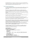
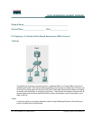
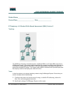
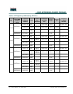
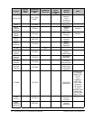

157 - 165 IP Telephony v1.0 SBA Table1: Copyright © 2005, Cisco Systems, Inc.
Table 1 IP Telephony Addressing Scheme
Pod
Hostname of
Cisco CME
router or
Switch
IP Address
on Ethernet
Interface
Type
DHCP
Pool
Exclusion
IP Network
for DHCP
Pool
Default
Router
Option
150
IP Address
on Serial
Interface
10.10.0.1 /24 Data
10.10.0.1-
10.10.0.10
10.10.0.0/24 10.10.0.1 10.19.0.1 /24
10.15.0.1/24 Voice
10.15.0.1-
10.15.0.10
10.15.0.0/24 10.15.0.1 10.10.0.1
CMERouter1
10.1.0.1/24 Mgmt
Pod 1
CMESwitch1 10.1.0.4/24 Mgmt 10.1.0.1
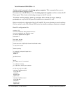
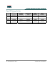
10.20.0.1 /24 Data
10.20.0.1-
10.20.0.10
10.20.0.0/24 10.20.0.1 10.19.0.2 /24
10.25.0.1/24 Voice
10.25.0.1-
10.25.0.10
10.25.0.0/24 10.25.0.1 10.20.0.1
CMERouter2
10.2.0.1/24 Mgmt
Pod 2
CMESwitch2 10.2.0.4/24 Mgmt 10.2.0.1
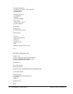
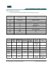
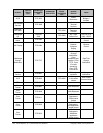
10.30.0.1 /24 Data
10.30.0.1-
10.30.0.10
10.30.0.0/24 10.30.0.1 10.39.0.1 /24
10.35.0.1/24 Voice
10.35.0.1-
10.35.0.10
10.35.0.0 24 10.35.0.1 10.30.0.1
CMERouter3
10.3.0.1/24 Mgmt
Pod 3
CMESwitch3 10.30.0.4/24 Mgmt 10.3.0.1
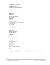
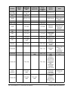
10.40.0.1 /24 Data
10.40.0.1-
10.40.0.10
10.40.0.0/24 10.40.0.1 10.39.0.2 /24
10.45.0.1/24 Voice
10.45.0.1-
10.45.0.10
10.45.0.0/24 10.45.0.1 10.40.0.1
CMERouter4
10.4.0.1/24 Mgmt
Pod 4
CMESwitch4 10.40.0.4/24 Mgmt 10.4.0.1