


149 - 165 IP Telephony v1.0 SBA Version 1: Copyright © 2005, Cisco Systems, Inc.
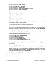
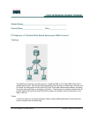
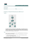
the PSTN/ POTS module. Connecting a regular phone to the port 8 of the PSTN/ POTS on
Atlas550 makes this phone reachable by the number 555-6008. This regular phone is used to
simulate a regular phone located at somewhere else in world.
Step 5: Testing and Troubleshooting
R1 and R2 are CME capable routers. R1 is located at the main office and R2 is located at the
remote office. The phones under R1 will register at R1 and the phones under R2 must
register at R2.
Playing the role of main site, R1 has a PSTN connection as well. This connection is
achieved through a PRI/T1 link and all the calls headed to the PSTN will be forwarded to
this link. Incoming PSTN calls will arrive over this link too and R1 is able to forward them
correctly.
The IP Phones are located at the user’s office where there is a PC. This PC may be using the
IP Phone as the access switch and thus, to access the data network.
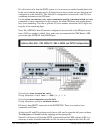
Try to place calls from one IP Phone to another, use the extension numbers showed on the
IP Phone’s display. The calls should be successful completed.
Try to place calls from the IP Phones to the regular phone (dial 95556008 from the IP
Phones) and from the regular phone to both IP Phones (dial 5555011 and 5555021 from the
regular phone). All calls should be working fine. Troubleshoot if necessary.
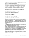
When working with the Telephony Company Cloud and something doesn’t work, it is useful
make sure the router is receiving the calls, that the Cloud is forwarding the calls well. If you
can see the calls process on the router, it means the clouds is doing its job and the problem is
probably the way the router is handling the incoming calls.
On this scenario, the connection with the company is simulated using an ISDN/T1 link
which is very similar to a real world situation. A very useful command when working with
an ISDN and PSTN is the debug isdn q931 command.
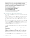
The show isdn status command can be used to make sure your ISDN connection is
established. A common output of this command at R1 when the PRI/T1 ISDN link is
established and up is similar to the following:
r1#sh isdn status
Global ISDN Switchtype = primary-ni
ISDN Serial1/0/0:23 interface
dsl 0, interface ISDN Switchtype = primary-ni
Layer 1 Status:
ACTIVE
Layer 2 Status:
TEI = 0, Ces = 1, SAPI = 0, State = MULTIPLE_FRAME_ESTABLISHED
Layer 3 Status:
0 Active Layer 3 Call(s)
Active dsl 0 CCBs = 0
The Free Channel Mask: 0x807FFFFF
Number of L2 Discards = 0, L2 Session ID = 5