


126 - 165 IP Telephony v1.0 Case Study 1: Copyright © 2005, Cisco Systems, Inc.
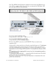
Step 3 Voice CME Router Configuration
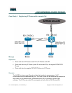
3.1 Preparing the Routers to handle the VLANs
Create and configure two sub-interfaces on the fastEthernet 0/0 of R1 and two sub-interfaces on the
fastEthernet 0/0 of R2. They will be used by the VLANs configured on the switch.
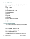
On R1:
R1(config)# int fa0/0
R1(config-if)# no ip address
R1(config-if)# no shutdown
R1(config)# int fa0/0.10
R1(config)# encapsulation dot1q 10
R1(config)# ip address 10.10.0.1 255.255.255.0
R1(config)# no shut
R1(config)# int fa0/0.15
R1(config)# encapsulation dot1q 15
R1(config)# ip address 10.15.0.1 255.255.255.0
R1(config)# no shut
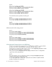
On R2:
R2(config)# int fa0/0
R2(config-if)# no ip address
R2(config-if)# no shutdown
R2(config)# int fa0/0.20
R2(config-subif)# encapsulation dot1q 20
R2(config-subif)# ip address 10.20.0.1 255.255.255.0
R2(config-subif)# no shut
R2(config-subif)# int fa0/0.25
R2(config-subif)# encapsulation dot1q 25
R2(config-subif)# ip address 10.25.0.1 255.255.255.0
R2(config-subif)# no shut
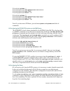
3.2 Configuring the DHCP Server on the Routers
The PCs and IP Phones will need IP Addresses. Configure the DHCP Pools on both R1 and
R2 routers so the routers will be able to teach IP Addresses to PCs and IP Phones.
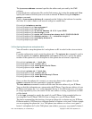
On R1:
R1(config)# ip dhcp pool DATA
R1(dhcp-config)# network 10.10.0.0 255.255.255.0
R1(dhcp-config)# default-router 10.10.0.1
R1(config)# ip dhcp pool VOICE
R1(dhcp-config)# network 10.15.0.0 255.255.255.0
R1(dhcp-config)# default-router 10.15.0.1
R1(dhcp-config)# option 150 ip 10.15.0.1
Note: The option ip 150 command is used to provide the ip address of the TFTP server.