


60 - 165 IP Telephony v1.0 Lab 4.1.3 Copyright © 2005, Cisco Systems, Inc.
This lab relies on labs 2.1.1, 2.1.2, 3.1.1, and 4.1.1, being successfully completed and loaded.
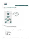
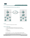
In this lab the ACME.com Company has decided that the analog connection to the PSTN is not
sufficient and, as a result, a PRI will be added to give additional capacity and to add DID capability.
The analog connection will be kept for a secondary connection to the PSTN. Configure the PRI with
the following settings.
Note: This lab uses the Adtran for simulating a PBX. Ensure you have the loaded the latest Adtran
IP Telephony configuration for this lab. If you are using the four port Quad T1/PRI card in the Adtran,
ensure the card is in slot four of the Adtran chassis. A special cable is used to connect the router T1
PRI port to the Adtran T1 port; a standard crossover or straight-through cable will not work. If you
have to make a cable, the RJ-45 connector pinouts are 1-4, 2-5, 4-1, 5-2.
There are multiple types of network modules (NMs) that can be used for T1 connections. If the router
has a network module it labeled as NM-DHV2-1T1/E1, the special commands are provided in the
lab.
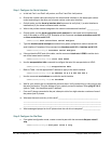
Step 1 Locate the T1 Port on the CME Router
a. Use the show diag command to view the hardware installed. Locate the T1 card in the
command output and determine what slot it is installed.
b. In what slot does the show diag command show the T1 card? ___________________
c. Perform a show running-config command from enable mode.
d. Does the T1 interface appear in the output? If so, how does it list _______________________
Note that the first number listed in the output is the slot number. This number is important in a
later command.
IMPORTANT: If the T1 interface does not appear, use the global configuration command card
type t1 slot 1 (where slot is the number documented previously). Note that this command is
only needed on the NM–HDV2-1T1/E1 module.
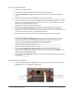
e. Look at the router ports and locate a port that is labeled CTRL T1/E1 or CTRLR T1. This is the
T1 port. The T1 module is integrated into or inserted into the NM-HDV card.
f. Connect a cable from the router T1 port to a T1 port on the Adtran (see table below for correct
Adtran Port number). The Adtran can have just one T1 port, or an optional card can be installed
that provides four more T1s. The optional card is labeled Quad T1/PRI. The cable that is used to
connect the router T1 port to any Adtran T1 port is a special cable. Refer to the note at the
beginning of the lab for connector pinouts.
Pod Number Adtran T1/PRI Port Number
1 T1 Network Module- Port
2 Quad T1/PRI – Port 1
3 Quad T1/PRI – Port 2
4 Quad T1/PRI – Port 3
5 Quad T1/PRI – Port 4