


Chapter 4 Adding the Cisco IP Phone 7914 Expansion Module
Installing the 7914 Expansion Module
4-10
Cisco IP Phone Administration Guide for Cisco CallManager 3.2, Cisco IP Phones 7960/7940/7910
78-10453-04
Note If you are installing a second 7914 Expansion Module, continue with Steps 3 and
4. Otherwise go to the “Connecting the Power Supply” section on page 4-11.
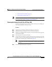
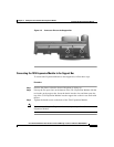
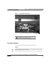
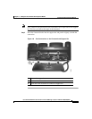
Refer to Figure 4-6 for an illustration of cable connections.
Step 3 Plug one end of the second RS 232 cable into the RS 232 jack with the “out” icon
underneath on the 1st Expansion Module.
Step 4 Plug the other end of the second RS 232 cable into the RS 232 jack with the “in”
icon underneath on the 2nd Expansion Module.
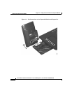
Figure 4-6 Cable Connections with Two Expansion Modules
1 RS 232 cable connection to the RS 232 jack on the IP Phone
2 RS 232 cable connection to the RS 232 jack on Expansion Module 1
3 2nd RS 232 cable connection to the RS 232 jack on Expansion Module 1
4 2nd RS 232 cable connection to the RS 232 jack on Expansion Module 2