


ND-71762 (E) CHAPTER 8
Page 85
Issue 2
MAINTENANCE PROCEDURE
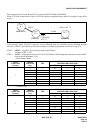
2.1 The Relationship between System Messages and Lamp Indications
When the system has detected a fault, the corresponding system message is displayed, at the same time, the related
lamp on the TOPU.
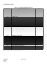
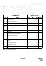
Table 8-1 shows the relationship between system messages and default lamp indications.
Note: ×: Default Lamp Indication.
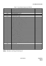
Table 8-1 System Messages and Lamp Indications on TOPU
SYSTEM MESSAGE LAMP ON THE TOPU
No. NAME MJ MN SUP PWR
13-A CCH Clock Failure ×
13-B
CCH C-Level Infinite Loop
(Permanent)
×
13-C CCH C-Level Infinite Loop (Temporary) ×
13-D
CCH Lock Up Failure
(Permanent)
×
13-E
CCH Lock Up Failure
(Temporary)
×
13-F
CCH B-Level Infinite Loop
(Permanent)
×
13-G CCH B-Level Infinite Loop (Temporary) ×
13-H CCS Link Failure (Permanent) ×
13-I CCS Link Failure (Temporary)
13-J
Restoration from CCS Link
Failure
13-K CCH Reset Interrupt Failure ×
17-A CCH MBR Key Turn ON
17-B CCH MBR Key Turn OFF