


ND-71762 (E) CHAPTER 2
Page 23
Issue 2
GENERAL INFORMATION FOR CCIS
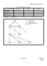
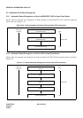
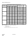
Table 2-5 shows the algorithm for changeover of input clocks from the DTI. The Table shows how the PLO selects
a specific route for input clocks according to the input clock status of four routes, thus establishing clock synchro-
nization. For example, in a case where Route 1, which has been selected due to a fault occurrence to clock input
Route 0, has also become faulty, Table 2-5 should be looked up as follows:
STEP 1: Look at Route 1 block under “Selected Route Before changeover” (the current input clock route) column.
STEP 2: Under “Each Route Input Clock Status” column, look for the block which shows that only Routes 0 and
1 are faulty.
STEP 3: Under “Route To Be Selected After Changeover” column located at the right extremity of the Table,
Route 2 is indicated in the block corresponding to the block found in Step 2.
If a route of which priority order is higher than the current route has been restored to normal, the route is changed
over to that specific route.