


CHAPTER 2 ND-71762 (E)
Page 2
Issue 2
GENERAL INFORMATION FOR CCIS
CHAPTER 2 GENERAL INFORMATION FOR CCIS
1. GENERAL
This chapter describes the functional outline of CCIS, hardware required for CCIS, and service features which can
be provided by CCIS.
2. DESCRIPTION OF CCIS
The modular architecture and wide range of voice and data features available with the digital PBX’s have been de-
veloped with emphasis on continued enhancement within a single PBX. In order to meet the growing demand for
further enhancement on a network level, NEC developed a networking system employing Common Channel Inter-
office Signaling (CCIS). The CCIS system links together individual PBX systems (nodes) to form a transparent
voice and data network which acts as a single large PBX, even though terminals within the network are, in fact, con-
nected to different PBX’s. Common Channel Interoffice Signaling (CCIS) derives its name from the fact that a sig-
naling channel (link), separate from voice and data channels, is provided between nodes for the sole purpose of
signal exchange. This signaling link is used in common by all voice and data links for exchange of information re-
lating to addressing (e.g. dialed digits, calling/called number); supervisory functions (e.g. call setup and termina-
tion); and network accounting and management (e.g. centralized billing and fault reporting.) This is unlike
conventional tie line networks which exchange signaling information over the same links as are for voice transmis-
sion (Associated Channel Interoffice Signaling.)
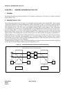
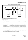
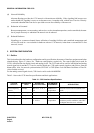
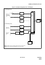
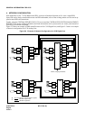
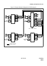
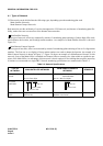
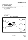
The block diagrams in Figure 2-1 and 2-2 illustrate the difference between Common Channel Interoffice Signalling
(CCIS) and Associated Channel (In-band) Interoffice Signaling (ACIS).
Figure 2-1 Associated Channel (In-Band) Interoffice Signaling
SIGNALING AND VOICE VIA THE SAME LINK
SND REG REG
CONTROL CONTROL
TRUNK TRUNK