


CHAPTER 8 ND-71762 (E)
Page 114
Issue 2
MAINTENANCE PROCEDURE
3. CCIS (Common Channel Interoffice Signaling) Line Fault
This paragraph explains the fault repair procedure when any of the faults shown in Table 8-1 occur to a specific
CCIS line.
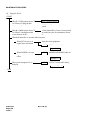
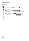
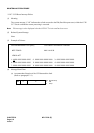
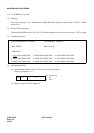
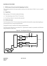
3.1 Check Point
When repairing a CCIS Line fault, consider the following:
(1) Check alarm lamps on the CCH or CCT circuit card
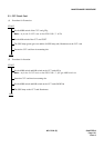
(2) By referring to Figure 8-5, check the cable connection.
3.2 CCIS Line Control
The CCH within the CCH/CCT circuit card controls the signal link of the interoffice common channel signaling sys-
tem and transmits/receives call processing information.
The signal link controls to send/receive the call processing information.
The call processing information is converted into No. 7 signal format for channel 1 (any channel) of the DTI before
being transmitted to a distant office.
Figure 8-5 Controlling the CCIS Line
MUX
CPU TSW
DTI
CCH
FRONT
CABLE
LT Cable
MDF
CCH MODEM
To CCIS Line
MODEM CABLE
CCT
LT Cable
MDF