


ND-71762 (E) CHAPTER 4
Page 35
Issue 2
INSTALLATION PROCEDURE
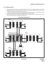
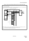
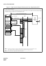
3.3 Cable Termination and Cross Connection from the MDF to the DSU
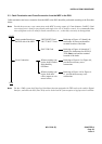
Cable termination and cross connection from the MDF to the DSU should be performed according to the flowchart
below:
Note: Provide the necessary cross connections at the MDF by using copper of 0.5 mm diameter (24AWG). Dual
core twisted wire is used for speech path, and single-core wire is used for control. It is recommended that
wires of different colors be used for trunks, station lines, etc., so that they can easily be distinguished.
Note: For the 1-IMG system: the Phase Lock Oscillator function equipped with TSW card can be used for Digital
Interface, and while the OSC (PA-CK14) card is used when the system requires a high precision oscillator.
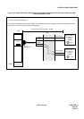
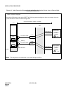
START
Check terminal location on
the PBX side of the MDF
24DTI/30DTI Card
24CCT/30CCT Card
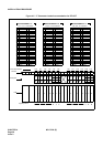
Referring to Figure 4-5, identify the
lead names for those cards and the
terminal location of the leads.
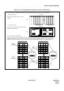
PLO/TSW Card Referring to Figure 4-6 through 4-7,
identify the lead names for the PLO/
TSW (
Note) card and the terminal
location of the leads.
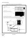
Cross Connection When accepting sync.
clocks from External
High-Stability
Oscillator
Referring to Figure 4-8 or Figure 4-9,
provide the necessary cross
connections.
When accepting sync.
clocks from other
office (master or sub-
master office)
Referring to Figure 4-10 or Figure 4-
11, provide the necessary cross
connections.
END