


CHAPTER 8 ND-71762 (E)
Page 120
Issue 2
MAINTENANCE PROCEDURE
5.2 DTI Circuit Card
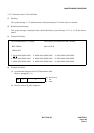
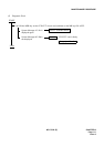
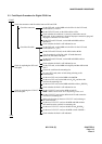
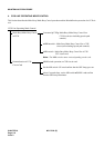
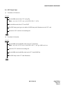
(1) Procedure for Extraction:
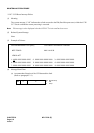
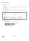
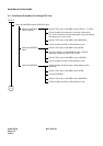
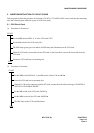
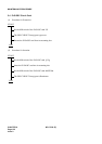
(2) Procedure for Insertion:
START
END
Set the MBR switch (SW01-0, 1) UP on the CCH card connected via the front cable with the DTI card.
Set the MB switch UP on the CCH card.
The OPE lamp (green) goes out and N-OPE lamp (red) illuminates on the CCH card.
Set the MB switch UP on the DTI card.
The OPE lamp (green) goes out and the N-OPE lamp (red) illuminates on the DTI card.
Remove the front cable of the DTI card.
Extract the DTI card from its mounting slot.
START
END
Set the MB switch of the DTI card UP .
Insert the DTI card into its mounting slot.
Connect the front cable between DTI and CCH card.
Set the MB switch of the DTI circuit card DOWN .
The OPE lamp of the DTI card illuminates.
Set the MB and MBR switch on the CCH card DOWN .
Confirm that the OPE lamp (green) illuminates on the CCH card connected with the DTI card via the
front cable.