


CHAPTER 4 ND-71762 (E)
Page 30
Issue 2
INSTALLATION PROCEDURE
CHAPTER 4 INSTALLATION PROCEDURE
1. GENERAL
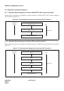
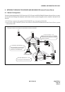
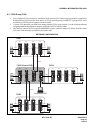
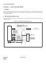
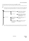
This chapter explains the installation procedure for connecting the PBX and the CCIS line. The scope of the instal-
lation procedure explained in this manual is shown in Figure 4-1. For procedures not explained in this manual, refer
to the Installation Manual:
2. PRECAUTIONS ON INSTALLATION
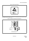
This manual provides “Static Caution” indicators (Figure 4-2) on pages where work involving static-sensitive com-
ponents is described.
Figure 4-1 Scope of the Installation Procedure
PBX
CCH MODEM
MDF/IDF
DTI
CCH
PLO
DSU
CCIS LINE
(DIGITAL LINE)
CCIS LINE
(ANALOG LINE)
CCT
Setting of Switch
Positions on the
Circuit Cards
(See Section 3.2)
Front Cable
Connection
between the
DTI and CCH
(See Section 3.4)
Cable Running from PBX
to the MODEM for Analog CCIS Line
(See Section 3.5)
Cross Connection
from MDF to DSU
(See Section 3.3)