


CHAPTER 4 ND-71762 (E)
Page 32
Issue 2
INSTALLATION PROCEDURE
3. INSTALLATION PROCEDURE
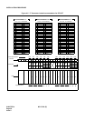
3.1 General Flow of Installation Procedure
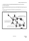
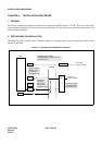
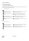
This section describes installation procedure divided into installation procedure items shown in Figure 4-1. The
work flow and the reference paragraphs are shown below.
• For Digital CCIS Line
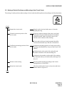
• For Analog CCIS Line
START
Setting of switch positions and
mounting of the circuit cards.
Refer to paragraph 3.2: “Setting of Switch Positions and
Mounting of the Circuit Cards”.
Cable running from the PBX to the
MDF.
Refer to “Cable Running from the PBX to MDF,
ATTCON, MAT, and SMDR” of the Installation
Manual.
Cable termination and cross
connection from the MDF to the DSU.
Refer to paragraph 3.3: “Cable Termination and Cross
Connection from the MDF to the DSU”.
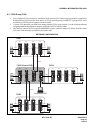
Front cable connection between DTI
and CCH.
Refer to Figure 4-12 “Front Cable Connections between
DTI/CCT and CCH”.
END
START
Setting of switch positions and
mounting of the CCH card.
Refer to paragraph 3.2: “Setting of Switch Positions and
Mounting of the Circuit Cards”.
Cable Running from the PBX to the
MODEM for Analog CCIS Line.
Refer to paragraph 3.5: “Cable Running from PBX to
the MODEM for Analog CCIS Line”.
END