


CHAPTER 4 ND-71762 (E)
Page 40
Issue 2
INSTALLATION PROCEDURE
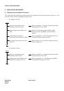
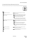
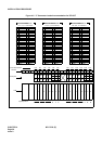
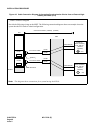
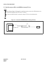
Figure 4-9 Cable Connection Diagram for Accepting Synchronization Clocks from an External High-
Stability Oscillator (PLO)
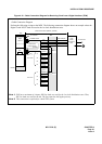
MDF
ISW
Cable Connection Diagram
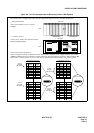
Provide the following wirings at the MDF. The following connection diagram shows an example where the
system has the PLO cards in a dual configuration.
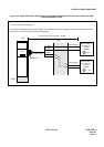
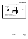
(External
Oscillator)
CLK
(External
Oscillator)
CLK
PCM Cable(IP)
PCM Cable(IP)
DCSA
DCSB
LT Connector Cable
EXCLK1
DCSB
DCSA
LT Connector Cable
EXCLK0
EXCLK1
PLO#1
EXCLK0
PLO#0
BASEU
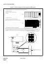
maximum 400 meters (1320feet) (24AWG)
Note:
This diagram shows connections for a system having dual PLOs.
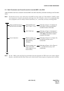
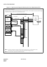
M-OSC #1
(Master Oscillator)
/EXT. OSC #1
M-OSC #0
(Master Oscillator)
/EXT. OSC #0