


CHAPTER 2 ND-71762 (E)
Page 6
Issue 2
GENERAL INFORMATION FOR CCIS
4. NETWORK CONFIGURATION
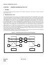
With application of No. 7 CCIS added to the PBX, a network of multiple functions as if it were a single PBX.
Since calls can be freely transferred between one PBX and another, most of the existing station services can be ap-
plied to inter-PBX call connections.
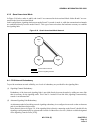
Further, using the CENTRALIZED BILLING-CCIS service and the CENTRALIZED SYSTEM MANAGEMENT
REPORT-CCIS service, billing information and fault information can be processed at one center point instead of
processing at each PBX concerned.
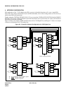
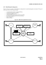
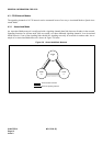
Figure 2-4 shows an example of PBX interoffice network for CCIS Digital Line, and Figure 2-5 shows an example
of network configuration for CCIS Analog Line.
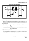
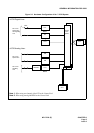
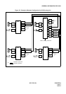
Figure 2-4 Example of Network Configuration for CCIS Digital Line
LC
LC
ATI
PBX
DTI
CCH
CCT
COT C.O
LC
LC
ATI
PBX
DTI
CCH
DTI
CCH
CCT
COT
DTI
CCH
C.O
PBXPBX
LC
LC
ATI
DTI
CCH
CCT
COT
C.O
LC
LC
ATI
DTI
CCH
CCT
COT
C.O
Failure, charging information
One channel of DTI shall be used for signals.
indicates a speech line.
indicates a signal line.