


ND-71762 (E) CHAPTER 4
Page 41
Issue 2
INSTALLATION PROCEDURE
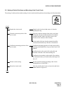
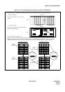
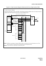
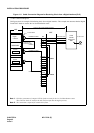
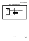
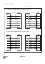
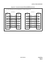
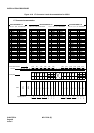
Figure 4-10 Cable Connection Diagram for Receiving Clock from a Digital Interface (TSW)
MDF
PBX
Cable Connection Diagram
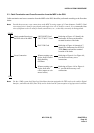
Perform the following wirings at the MDF. The following connection diagram shows an example where the
Digital Trunk POUT leads are used as the 1st clock distribution route.
PCM
Carrier
Equipment/
DSU
CLK
PCM Cable(2P)
LT Connector
PLO
PLO
TSW
BASEU
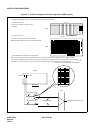
maximum 200 meters (660feet) (24AWG)
to other node
RA
RB
TA
TB
POUTA
POUTB
DIU0A0
DIU0B0
DIU1A0
DIU1B0
DIU2A0
DIU2B0
DIU3A0
DIU3B0
DIU0A1
DIU0B1
DIU1A1
DIU1B1
DIU2A1
DIU2B1
DIU3A1
DIU3B1
#1
#2
#3
#4
#1
#2
#3
#4
for PLO #0
for PLO #1
Installation Cable
Installation Cable
maximum100
meters(330 feet)
Digital
Interface
Note 1
Note 1:
Note 2:
Note 2
PLO has a maximum of 4 inputs. DIU0xx leads are used for the 1st clock distribution routs. Thus,
DIU3xx leads are used for the 4th. The first input has the highest priority.
This connection is required for a dual-TSW system.
(24AWG)