


CHAPTER 4 ND-71762 (E)
Page 42
Issue 2
INSTALLATION PROCEDURE
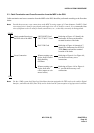
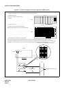
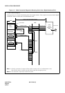
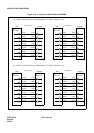
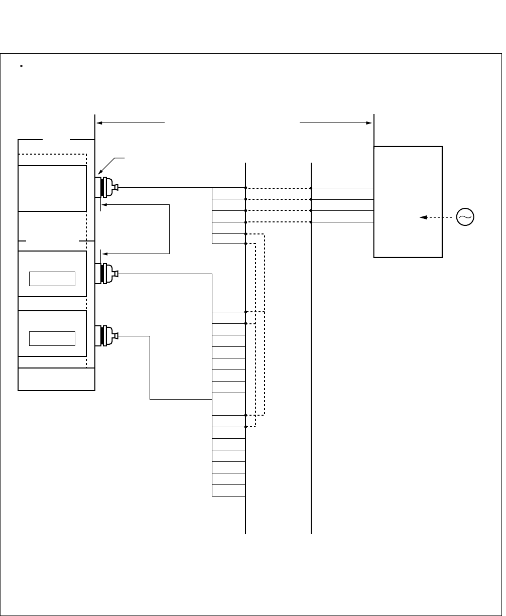
Figure 4-11 Cable Connection Diagram for Receiving Clock from a Digital Interface (PLO)
DIU0A1
DIU0B1
DIU1A1
DIU1B1
DIU2A1
DIU2B1
DIU3A1
DIU3B1
DIU0A0
DIU0B0
DIU1A0
DIU1B0
DIU2A0
DIU2B0
DIU3A0
DIU3B0
RA
RB
TA
TB
POUT A
POUT B
PCM Cable (2P) to other node
PCM
Carrier
Equipment
DSU
CLK
Note 1:
Note 2
Note 1
PLO has a maximum of 4 inputs. DIU0xx leads are used for the 1st clock distribution routes.
Thus, DIU3xx leads are used for the 4th. The first input has the highest priority.
Note 2:
The connection is required for a dual PLO system.
MDF
maximum 100
meters (330 feet)
(24AWG)
Installation Cable
LT Connector
Installation Cable
Installation Cable
EXCLK1
PLO#1
EXCLK0
PLO#0
Digital
Interface
IMG
IMG/ISWM
maximum 200 meters (660feet) (24AWG)
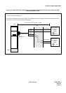
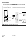
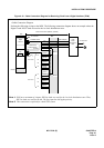
This figure shows an example of distributing clock from a digital interface. This example also assumes that the Digital
Trunk POUT leads are used as the 1st clock distribution route.
Cable Connection Diagram