


ND-71762 (E) CHAPTER 8
Page 87
Issue 2
MAINTENANCE PROCEDURE
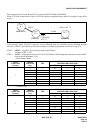
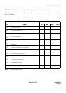
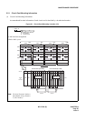
2.2.1 Circuit Card Mounting Information
(1) Circuit Card Mounting Information
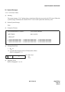
Accommodated location information of each circuit card is described by a hexadecimal number.
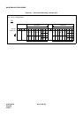
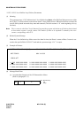
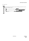
Figure 8-1 Circuit Card Mounting Location (1/2)
FRONT VIEW
TOPU
IMG0
FANU
BASEU
LPM
U2 U3
U0 U1
U2 U3
U0 U1
MG01
MG00
TOPU
IMG2
FANU
BASEU
DUMMY
U2 U3
U0 U1
U2 U3
U0 U1
MG05
MG04
TOPU
IMG3
FANU
BASEU
DUMMY
U2 U3
U0 U1
U2 U3
U0 U1
MG07
MG06
TOPU
IMG1
FANU
BASEU
TSWM
U2 U3
U0 U1
U2 U3
U0 U1
MG03
MG02
PIM3
PIM2
PIM1
PIM0
00 02 04 05 06 07 08 09 10 11 12 13 14 15 16 17 18 19 20 21 22 23
16 16 16 16 16 16 32 32 32 16 16 16 16 16 16 32 32 32
MUX (PH-PC36) 0
MUX (PH-PC36) 1
192 TS
PWR
PWR
Unit Number (U = 0/2) Unit Number (U = 1/3)
Control Control
1-IMG/4-IMG system
192 TS
16 16 16 16 16 16
Number
of
Time Slots
Slots No.
PIM
(16)(16)
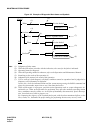
(a) MG and Unit configuration
1 : XX00 00
MG: Module Group Number
U: Unit Number
G: Group Number
MG
UG
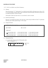
LP0 LP2 LP4 LP6
Note: LP (Local Partition Number),
MG (Module Group Number)
U (Unit Number)