


CHAPTER 6 ND-71762 (E)
Page 68
Issue 2
BASIC DATA ASSIGNMENT
2.2 Basic Data Assignment Procedure
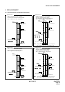
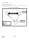
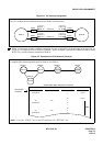
This section explains “How to program necessary data associated with a CCIS network” using the following exam-
ple. Note that Node A is your office.
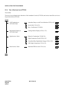
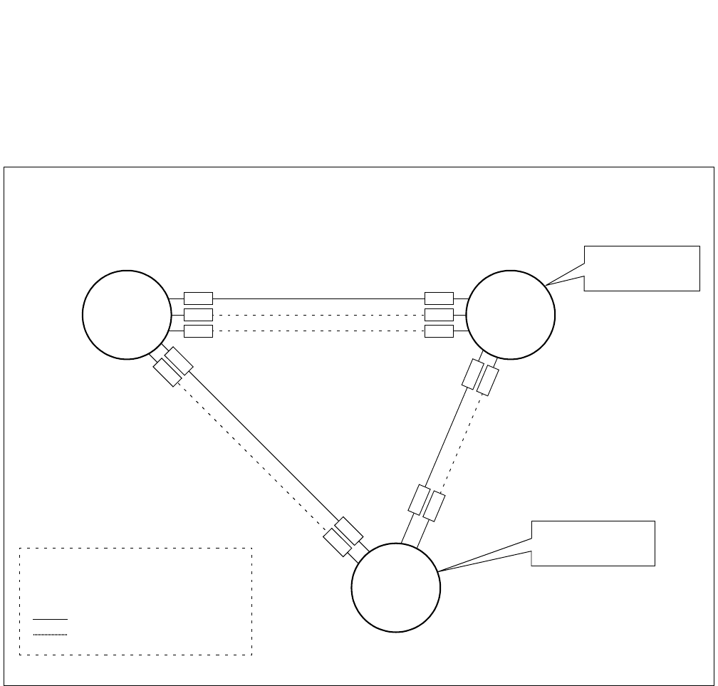
Figure 6-1 Example of a CCIS Network
• In this figure, five letters such as AAAAA, represent mounting location of CCT card or CCH card.
CCH1: BBBBB
Node A
CCH0: AAAAA
RT11
Centralized
Billing Office
CCH2: CCCCC
RT12
PC = 30
“830”
Node C
PC = 10
“810”
PC = 20
“820”
Node B
Centralized
Management Office
PC : Point Code
RT : Route
CCH : Common Channel Handler
“8xx” : Office Code
: Speech Line
: Signaling Line
TK4
TK5
CCH1’: EEEEE
CCH0’: DDDDD
TK7
TK8