


ND-71762 (E) CHAPTER 2
Page 13
Issue 2
GENERAL INFORMATION FOR CCIS
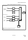
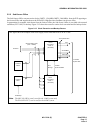
4.3.2 Quasi-Associated Mode
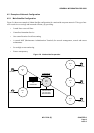
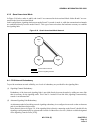
In Figure 2-10 below, nodes A and B, and A and C are connected in the Associated Mode. Nodes B and C are con-
nected in the Quasi-Associated Mode.
In this configuration, signaling data between nodes B and C is routed via node A, while the communication channels
are established directly between nodes B and C. This type of network reduces the hardware necessary to establish
the signaling links.
Figure 2-10 Quasi-Associated Mode Network
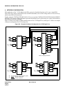
4.4 CCIS Network Redundancy
To provide maximum network reliability, two levels of redundancy are provided for the signaling links.
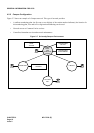
(1) Signaling Channel Redundancy
Redundancy of the inter-node signaling links is provided directly between the nodes by adding one more link
than is necessary for the signaling traffic. This is the N+1 method. If one link fails, signaling is automatically
routed via an alternate link.
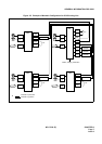
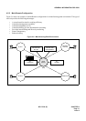
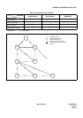
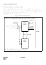
(2) Alternate Signaling Path Redundancy
An alternate method of providing network signaling redundancy is to configure the network so that an alternate
path is provided between the nodes.
In the network shown in Figure 2-9, if the signaling link(s) directly connecting nodes B and C should fail, the
signaling would automatically be reconnected via node A without loss of service. (Node A would be designated
as the Signaling Transfer Point [STP]).
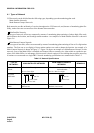
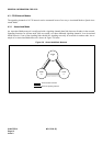
Communication Channel
Common Signaling Channel
NODE
A
NODE
B
NODE
C