


CHAPTER 4 ND-71762 (E)
Page 38
Issue 2
INSTALLATION PROCEDURE
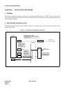
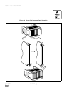
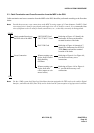
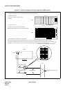
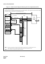
Figure 4-7 PLO Pin Assignment for Receiving Clock (4-IMG System)
00 0102 03 0405 0607 080910 11 1213 14 15 161718 1920 21 22 23
Front View
TSWM
TSWM
TSW
Backplane
PLO input leads appear on the LT connectors labeled EXCLK0 and EXCLK1.
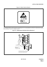
PLO mounting slots
PLO card is mounted in slots 21 and 23
of TSWM.
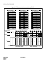
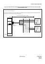
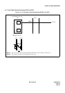
LT cable connectors
Connect LT cables to the connectors labeled
EXCLK0 and EXCLK1 on the TSWM backplane.
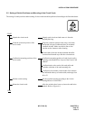
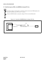
EXCLK0/EXCLK1 connector Pin Assignment
Pins are assigned as follows on EXCLK0/EXCLK1 connector. When clock is distributed from a digital interface,
use one pair of DIUxxx leads among a maximum of 4 inputs. DIU leads have the following precedence: DIU0xx(High)
DIU3xx(Low). On the contrary, to receive clock from an external high-stability osillator, use DCSxx leads.
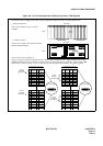
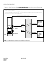
PLOEXCLK1
EXCLK0
PLO
EXCLK0
EXCLK1
34PH EXCLK CA-A
34PH EXCLK CA-A
REAR VIEW
EXCLK0
EXCLK1
TSWM
MDF
Installation Cable To Digital Interface and/or DCS
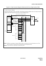
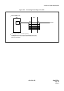
34PH EXCLK CA-A Cable Lead Accommodation
26
27
28
29
30
31
32
33
34
35
36
37
38
1
2
3
4
5
6
7
8
9
10
11
12
13
FM1
FM0
SYN1B
SYN0B
DIU3B
DIU2B
DIU1B
DIU0B
DCSB
E
E
SYN1A
SYN0A
DIU3A
DIU2A
DIU1A
DIU0A
DCSA