


ND-71762 (E) CHAPTER 8
Page 115
Issue 2
MAINTENANCE PROCEDURE
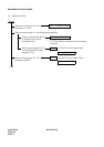
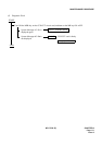
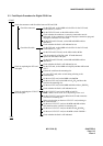
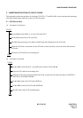
3.3 Fault Repair Procedure for Digital CCIS Line
START
END
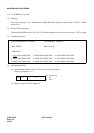
On the DTI card, set the MBR switch UP . On the CCH card,
set the SW01-0, 1 UP .
On the DTI/CCH card, set the MB switches UP .
Check whether the connector is correctly connected or not for
both cards. If the connection is found an improper connection, plug and
unplug the connector for a few times.
On the DTI and CCH cards, set the MB and MBR switches
DOWN .
Check whether the fault is still indicated or not.
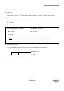
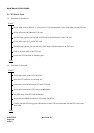
On the DTI card, set the MBR switch UP . On the CCH card,
set the SW01-0, 1 UP .
On the DTI and CCH card, set the MB switches UP .
Test the continuity of the flat cable. If found abnormal,
replace the flat cable with spare.
On the DTI and CCH cards, set the MB and MBR switches
DOWN .
Check whether the fault is still indicated or not.
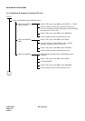
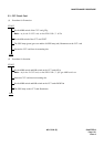
On the DTI card, set the MBR switch UP and then MB switch
UP .
Extract the card from the mounting slot.
On a new DTI card, make switch setting referring to the
extracted card.
On the new DTI card, set the MBR switch UP .
On the new DTI card, set the MB switch UP and insert the
card into the mounting slot.
On the new DTI card, set the MBR and MB switches DOWN .
Check whether the fault is still indicated or not.
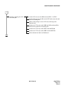
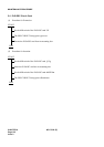
On the CCH/CCT card, set the MBR switch UP.
Note : MBR switch s name varies depending on the card.
On the CCH/CCT card, set the MB switch UP and extract the
card from its mounting slot.
Make switch setting on the new CCH/CCT card, referring to
the card extracted.
On the new CCH/CCT card, set the MBR and MB switches
UP and insert the card into its mounting slot.
On the new CCH/CCT card, set the MB switch DOWN .
On the new CCH/CCT card, set the MBR switch DOWN .
Check whether the fault is still indicated.
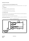
Check the connectors and flat cables between DTI and CCH.
Check the connector
Check the flat cable
Check by replacing the DTI card
with spare
Check by replacing the CCH/CCT
card with spare