


CHAPTER 2 ND-71762 (E)
Page 18
Issue 2
GENERAL INFORMATION FOR CCIS
5.2.3 Receiver Office and Local Receiver Office
For connecting the DTI (Digital Trunk Interface) of the user office to the DTI of a higher-ranking office, the user
office must establish clock synchronization with the higher-ranking office concerned.
A Receiver Office or a Local Receiver Office extracts carrier clocks (24DTI: 1.544 MHz/30DTI: 2.048 MHz) from
the DTI opposing to the higher-ranking office and establishes clock synchronization with the higher-ranking office
by supplying the extracted carrier clocks to the PLO/TSW (Subordinate oscillator) in the user office.
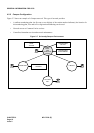
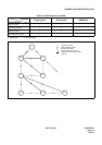
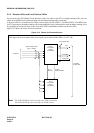
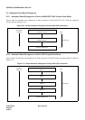
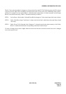
Figure 2-13 shows the routes for clock extraction.
Figure 2-13 Routes for Extracted Clocks
Two systems each
ACT
8 kHz (FH)
To Switch
System side
PLO 1
(PH-CK16)
/TSW 1
(PH-SW10)
From DTI
Clock receiving route
(max. 4 routes)
PLO 0
(PH-CK16)
/TSW 0
(PH-SW10)
32.768 MHz
ACT
Change
CLOCK
Synchronization
This figure shows an example of the clock supply routes when PLO0/TSW0 is in ACT side.
Note: The TSW (PH-SW10) card is used for the 1-IMG system only.
The PLO (PH-CK16) card is used for the 4-IMG system.