


ND-71762 (E) CHAPTER 2
Page 19
Issue 2
GENERAL INFORMATION FOR CCIS
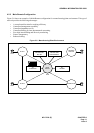
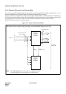
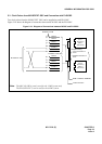
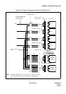
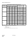
5.3 Clock Pulses from M-OSC/EXT. OSC and Connection with PLO/OSC
Two clock pulses from the M-OSC/EXT. OSC can be supplied to each PLO/OSC.
Figure 2-14 shows the diagram of connection between the M-OSC and the PLO/OSC.
Figure 2-14 Diagram of Connections between M-OSC and PLO/OSC
IDF/MDF for PCM
M-OSC/EXT. OSC
Route 3
Route 2
Route 1
Route 0
M-OSC 1
M-OSC 0
Route 3
Route 2
Route 1
Route 0
M-OSC 1
M-OSC 0
Installation Cable (25p)
0
Backplane wiring
Cross-connection of
PLOs
BWB of TSWM or ISWM/PIM
Cable-connection
Multiple-connection of
DTIs
PLO 1
(PH-CK17)
/OSC 1
(PA-CK14)
PLO 0
(PH-CK17)
/OSC 0
(PA-CK14)
1
Note: The OSC (PA-CK14) card is used for the 1-IMG system only.
The PLO (PH-CK17) card is used for the 4-IMG system.