


D-5
Cisco ATA 186 and Cisco ATA 188 Analog Telephone Adaptor Administrator’s Guide (SCCP)
OL-3141-01
Appendix D SCCP Call Flows
Call Flow Scenarios for Successful Calls
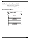
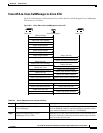
Cisco ATA-to-Cisco CallManager-to-Cisco ATA
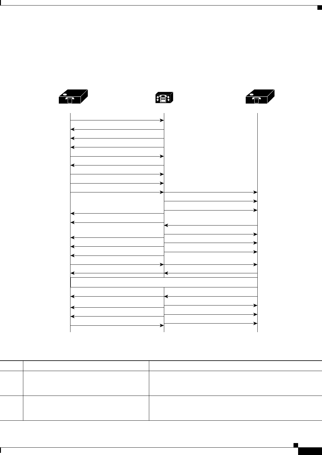
Figure D-2 illustrates the call flow between Cisco ATA 1 and Cisco ATA 2 through a Cisco CallManager.
The call flow is as follows:
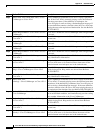
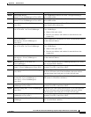
Figure D-2 Cisco ATA-to-Cisco CallManager-to-Cisco ATA
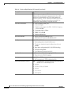
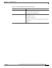
Table D-2 Action Descriptions for Second Call Flow
Step Station Call Info Description
Step 1
Station OffHook—Cisco ATA 1 to
Cisco CallManager
Cisco ATA 1 informs the Cisco CallManager that Cisco ATA 1 is
not in an OffHook condition, and simultaneously provides calling
party number information to the Cisco CallManager.
Step 2
Station Set Lamp (Steady)—Cisco
CallManager to Cisco ATA 1
When the Cisco ATA detects that one port is in an off-hook state,
the Cisco ATA turns on the lamp, then turns off the lamp once both
ports are in the on-hook state.
Cisco ATA
Station OffHook
Cisco CallManager
82054
V
Cisco ATA
V
Station Display Text
Station Set Lamp (Steady)
Station Start Tone (Inside Dial Tone)
Station Keypad Button
Station Stop Tone
Station Keypad Button
Station Keypad Button
Station Keypad Button Station Call Info
Station Set Lamp (Blink)
Station Set Ringer (Inside Ring)
Station Call Info
Station Start Tone (Alerting)
Station Off Hook
Station Set Ringer (Off)
Station Stop Tone
Station Open Receive Channel
Station Cell Info
Station Open Receive Channel Ack
Station Close Receive Channel
Station Stop Media Xmission
Station Set Lamp (Steady)
Station Open Receive Channel
Station Start Media Xmission
Station Set Lamp (Off)
Station Set Lamp (Off)
Station Close Receive Channel
Station On Hook
Station Stop Media Xmission
Station Open Receive Channel Ack
Station On Hook
Station Start Media Xmission
User Information Exchange