


R5976214 VisuPlus Video Insertion Unit June 2003
9-2
9.2 Table of Figures
Figure 1-1 CEE 7 plug 1-5
Figure 1-2 ANSI 73.11 plug 1-5
Figure 2-1 V
ISU
PLUS
– EOS setup 2-2
Figure 2-2 V
ISU
PLUS
– standalone setup 2-3
Figure 3-1 front view of V
ISU
PLUS
3-2
Figure 3-2 rear view of V
ISU
PLUS
3-3
Figure 3-3 mains connection of V
ISU
PLUS
3-5
Figure 3-4 digital output unit (DVI) 3-6
Figure 3-5 DVI-D to DVI-D cable 3-6
Figure 3-6 numbering of output units 3-7
Figure 3-7 output units in multiple V
ISU
PLUS
3-7
Figure 3-9 digital output unit 3-8
Figure 3-10 PanelLink cable 3-8
Figure 3-11 analog output unit 3-9
Figure 3-12 D15 – D15 cable 3-10
Figure 3-13 D15 – BNC cable 3-10
Figure 3-14 video input unit 3-11
Figure 3-15 numbering of input units 3-11
Figure 3-16 input units in multiple V
ISU
PLUS
3-11
Figure 3-17 RGB input unit 3-12
Figure 3-18 processor board 3-13
Figure 3-19 V
ISU
PLUS
load cable 3-14
Figure 3-20 V
ISU
PLUS
reset cable 3-14
Figure 3-21 BNC - BNC cable 3-15
Figure 3-22 data and control cabling: V
ISU
PLUS
– EOS setup, digital 3-17
Figure 3-23 data and control cabling: Visu
Plus
– Eos setup, analog 3-18
Figure 3-24 data and control cabling: Visu
Plus
– standalone setup, analog 3-19
Figure 4-1 display without video switcher 4-6
Figure 4-2 display with video switcher 4-6
Figure 6-1 data tables of Visu
Plus
6-3
Figure 6-2 numbering of OPU’s and projection modules 6-9
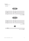
Figure 7-1 D9 female pin assignment 7-6
Figure 7-2 D9 male pin assignment 7-6
Figure 7-3 BNC connector pin assignment 7-6
Figure 7-4 DVI in and out connector PanelLink pin assignment 7-7
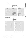
Figure 7-6 MDR26 in connector PanelLink pin assignment 7-7
Figure 7-7 MDR26 out connector PanelLink pin assignment 7-8
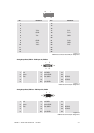
Figure 7-8 RGB male connector pin assignment 7-8
Figure 7-9 RGB female connector pin assignment 7-8
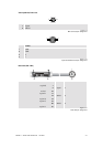
Figure 7-10 BNC connector pin assignment 7-9
Figure 7-11 4-pole mini-DINconnector pin assignment 7-9
Figure 7-12 reset cable pin assignment 7-9
Figure 7-13 load cable pin assignment 7-10