


R5976214 VisuPlus Video Insertion Unit June 2003
3-19
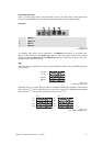
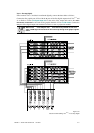
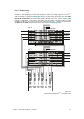
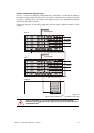
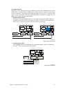
VisuPlus – standalone setup (digital and analog)
If VISU
PLUS
is setup in a standalone configuration and is controlled by a control PC the cabling of
the digital or analog output units follows the same scheme. Therefore just the cabling for the ana-
log setup is explicitly given. The cabling of the digital setup has to be established accordingly.
Connect the data cables as follows:
Connect the
out ports of the analog output units with the analog projection modules or CRT
monitors.
RGB in RGB out
VISU+
OPU
RGB in RGB out
VISU+
OPU
RGB in RGB out
VISU+
OPU
RGB in RGB out
VISU+
OPU
Control PC
Visu I
Plus
VIDEO in VIDEO out SVHS outSVHS in
VISU+
VIDEO IPU
VIDEO in VIDEO out SVHS outSVHS in
VISU+
VIDEO IPU
RGB in RGB out
VISU+
RGB IPU
RGB in RGB out
VISU+
RGB IPU
RGB in RGB out
VISU+
OPU
RGB in RGB out
VISU+
OPU
RGB in RGB out
VISU+
OPU
RGB in RGB out
VISU+
OPU
RS232 in RS232 outHS in HS out VS in
to proj
RESET in RESET out
VISU+
CPU
Visu II
Plus
VIDEO in VIDEO out SVHS outSVHS in
VISU+
VIDEO IPU
VIDEO in VIDEO out SVHS outSVHS in
VISU+
VIDEO IPU
RGB in RGB out
VISU+
RGB IPU
RGB in RGB out
VISU+
RGB IPU
RS232 in RS232 outHS in HS out VS in
to proj
RESET in RESET out
VISU+
CPU
4 x to projector
4 x to projector
V
ideo/RGB
sources
Video/RGB
sources
Figure 3-23
data and control cabling: Visu
Plus
– standalone setup, analog
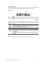
Under no circumstances, connect any signal to either one of the sync-BNC
connectors (HS in [2], to proj. [3], VS in [4], to proj. [5]) on the processor board of
the stand-alone VISU
PLUS
.