


R5976214 VisuPlus Video Insertion Unit June 2003
4-6
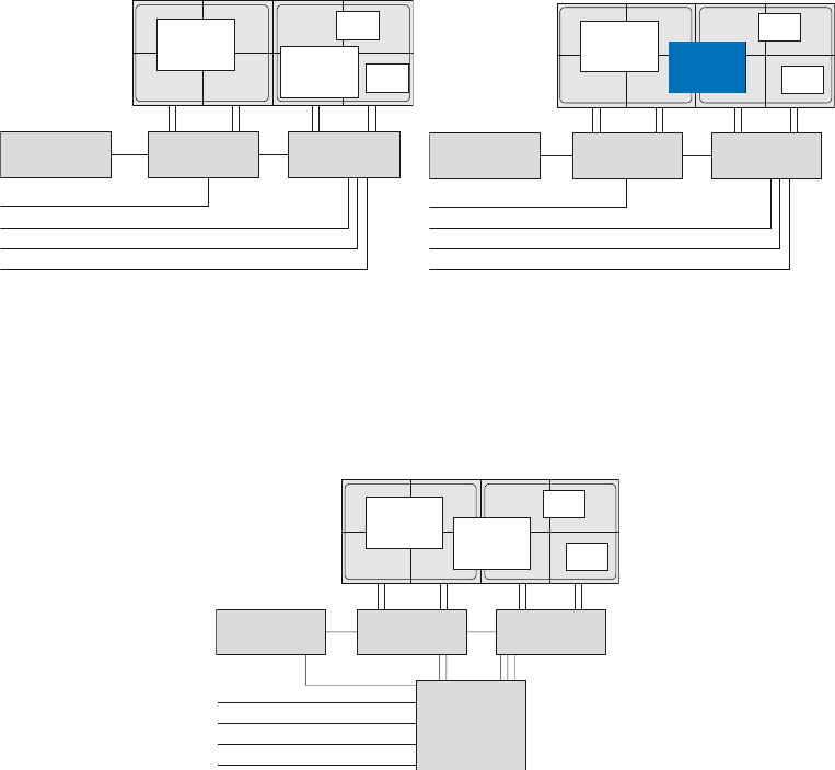
4.1.4 Video Switcher
Integrating a video switcher improves the possibilities of moving video and RGB windows on the
Display Wall. A connected video or RGB source can then not only be displayed in the display
section of one V
ISU
PLUS
but can be moved within the whole area of all VISU
PLUS
connected to the
source via the video switcher. The figures below illustrate the possibilities to display video and
RGB windows without and with video switcher:
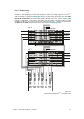
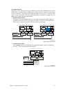
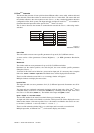
No video switcher is used:
The display of the video and RGB windows is restricted to the projection modules, which are
connected to one specific V
ISU
PLUS
(left image). If a window is moved over the borders of the
display area, no content can be shown in the concerned area (right image):
V
ISU
P
LUS
I display area V
ISU
P
LUS
II display area
V
ISU
P
LUS
IV
ISU
P
LUS
II
Eos /
CPControl
1
2
4
3
Video 1
Video 2
Video 3
Video 4
V
ISU
P
LUS
I display area V
ISU
P
LUS
II display area
V
ISU
P
LUS
IV
ISU
P
LUS
II
1
4
3
Video 1
Video 2
Video 3
Video 4
Eos /
ControlPC
2
Figure 4-1
display without video switcher
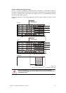
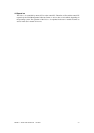
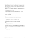
A video switcher is used:
Video and RGB windows can be displayed on all projection modules, which are connected to
any V
ISU
PLUS
that is connected to the video switcher.
V
ISU
P
LUS
I display area V
ISU
P
LUS
II display area
V
ISU
P
LUS
I V
ISU
P
LUS
II
Video switcher
Video 1
Video 2
Video 3
Video 4
1
2
4
3
Eos /
CPControl
Figure 4-2
display with video switcher