


R5976214 VisuPlus Video Insertion Unit June 2003
3-16
3.3 Starting Up
3.3.1 Connecting
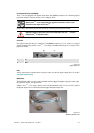
Plug in the power cable on the back panel of your VISU
PLUS
. Please refer to section 3.2.1 Power
Supply
!
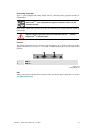
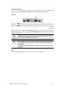
Connect the serial port of the Multiport I/O Card of E
OS and the control PC respectively with the
RS232 in port of the processor board. If more than one VISU
PLUS
is used connect the RS232 out port
of the processor board of the first V
ISU
PLUS
with the RS232 in port of the processor board of the
next V
ISU
PLUS
and so on, see section 3.2.7 Processor Board.
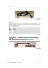
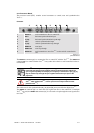
Connect the parallel port of the E
OS and the control PC respectively with the RESET in port of the
processor board of V
ISU
PLUS
. If more than one VISU
PLUS
is used connect the RESET out port of the
processor board of the first V
ISU
PLUS
with the RESET in port of the processor board of the next
V
ISU
PLUS
and so on, see section 3.2.7 Processor Board.
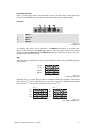
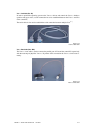
Connect the video or RGB sources with the respective
in port on the video or RGB input unit, refer
to section
3.2.5 Video Input Unit and 3.2.6 RGB Input Unit.
Interfaces and long cabling can influence the image quality (sharpness and color).
To reduce the color degradation, one can tune the interface while its image is
being displayed directly on a projector, before connecting it to the input of the
V
ISU
PLUS
! This takes some time, but it pays off in the end!
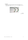
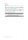
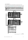
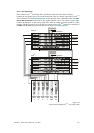
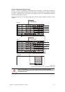
For the connection of cables for the graphical data three different setups of VISU
PLUS
have to be
distinguished, depending on analog or digital output units and on E
OS or standalone setup: