


R5976214 VisuPlus Video Insertion Unit June 2003
3-18
VISU
PLUS
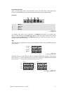
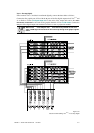
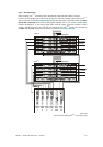
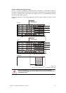
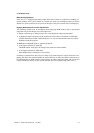
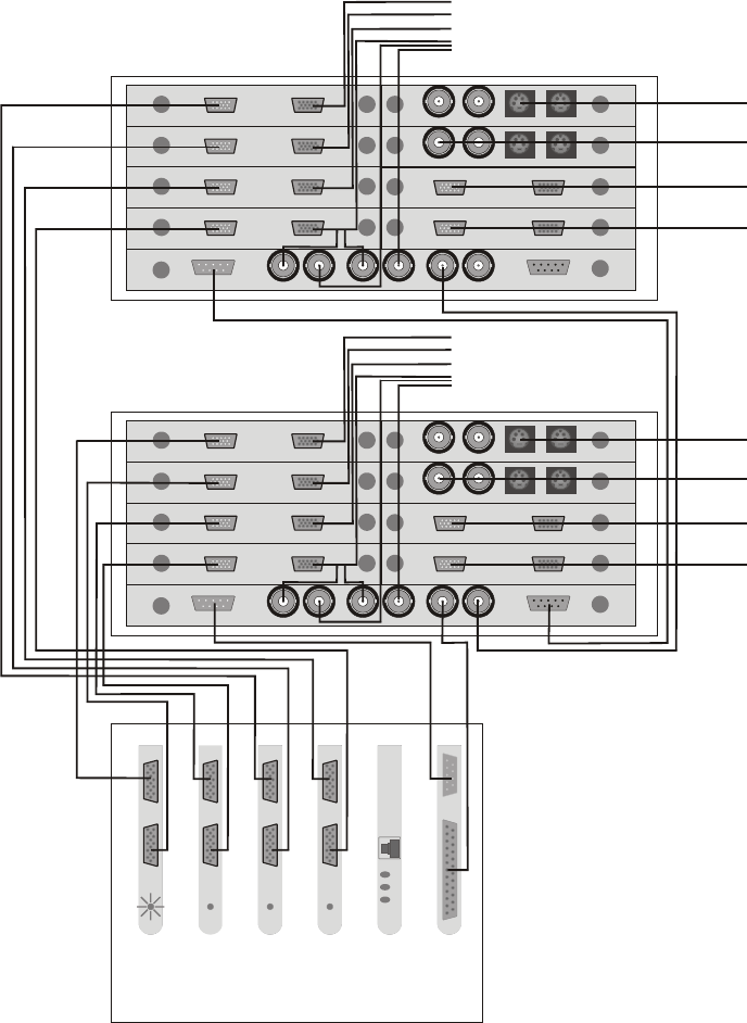
– EOS setup (analog)
If EOS controls VISU
PLUS
and analog data is transferred, connect the data cables as follows:
Connect the first graphic port of E
OS with the in ports of the first analog output unit of VISU
PLUS
and so on. Refer to section 3.2.4 Analog Output Unit for the order of the output units and to the user’s
manual Eos X Terminal
for the order of the graphic channels of EOS, see section 7.3 Order Codes.
Connect the
out ports of the analog output units with the analog projection modules or CRT
monitors. The Hsync and Vsync of the last used output of each V
ISU
PLUS
needs to be connected to
the
HS in and the VS in of the processor boards, see section 3.2.4 Analog Output Unit.
RGB in RGB out
VISU+
OPU
RGB in RGB out
VISU+
OPU
RGB in RGB out
VISU+
OPU
RGB in RGB out
VISU+
OPU
Eos
Graph.
Card
1
Multi-
port
I/O
Net-
work
Card
Graph.
Card
4
Graph.
Card
3
Graph.
Card
2
V
isu I
Plus
VIDEO in VIDEO out SVHS outSVHS in
VISU+
VIDEO IPU
VIDEO in VIDEO out
SVHS outSVHS in
VISU+
VIDEO IPU
RGB in RGB out
VISU+
RGB IPU
RGB in RGB out
VISU+
RGB IPU
RGB in RGB out
VISU+
OPU
RGB in RGB out
VISU+
OPU
RGB in RGB out
VISU+
OPU
RGB in RGB out
VISU+
OPU
RS232 in RS232 outHS in HS out VS in
to proj
RESET in RESET out
VISU+
CPU
Visu II
Plus
VIDEO in VIDEO out SVHS outSVHS in
VISU+
VIDEO IPU
VIDEO in VIDEO out SVHS outSVHS in
VISU+
VIDEO IPU
RGB in RGB out
VISU+
RGB IPU
RGB in RGB out
VISU+
RGB IPU
RS232 in RS232 outHS in HS out VS in
to proj
RESET in RESET out
VISU+
CPU
4 x to projector
4 x to projector
V
ideo/RGB
sources
Video/RGB
sources
Figure 3-22
data and control cabling: Visu
Plus
– Eos setup, analog