R5976214 VisuPlus Video Insertion Unit June 2003
3-3
The Back
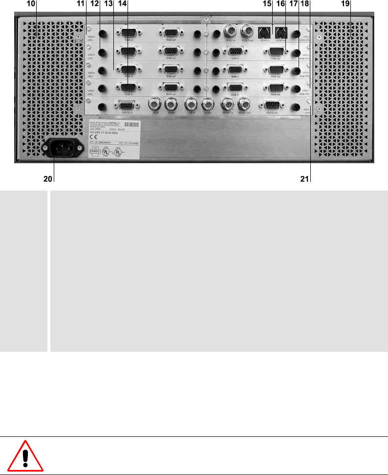
The back of your VISU
PLUS
looks like this or similar:
10, 19 air supply
11 output card 0
12 output card 1
13 output card 2
14 output card 3
15 input card 0
16 input card 1
17 input card 2
18 input card 3
20 mains connection
21 processor board
Figure 3-2
rear view of V
ISU
P
LUS
On the lower left hand side there is the mains connection [20].
In the left middle there are up to four
output cards [11-14], lined up one under each other. In the
right middle there are up to four
input cards [15-18], lined up one under each other. Under the in-
put and output cards, the
processor board [21] is located.
To protect VISU
PLUS
from overheating, the air supply openings in the case shall be
kept free of obstructions!


