


R5976214 VisuPlus Video Insertion Unit June 2003
6-3
6.3 VISU
PLU S
Internals
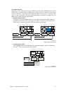
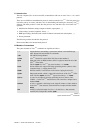
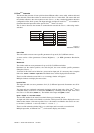
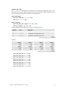
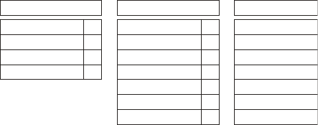
The internal data structure is been split into three different tables: source table, window table and
input unit table. These three tables are stored on each V
ISU
PLUS
in the chain. The source table and
the window table have the same content on each V
ISU
PLUS
, as they contain information about the
configuration of the whole system. The input unit table is unique on each V
ISU
PLUS
as it contains in-
formation about the input units of the specific V
ISU
PLUS
where it is stored.
This is done to decrease the amount of communication towards the V
ISU
PLUS
when using matrix-
switchers.
Source TableWindow Table
Source 0 parametersWindow 0 parameters 0
Source 1 parametersWindow 1 parameters -1
Source 2 parametersWindow 2 parameters 3
Source 3 parametersWindow 3 parameters 4
Source 4 parametersWindow 4 parameters -1
………
Source 63 parametersWindow 63 parameters -1
Input Unit Table
0IPU x+0 parameters
3
IPU x+1 parameters
-1
IPU x+2 parameters
2IPU x+3 parameters
Figure 6-1
data tables of Visu
Plus
Source Table
The source table can store source specific parameters for up to 64 (0..63) different sources.
A source can be a video (parameters: Contrast, Brightness, …) or RGB (parameters: Resolution,
Phases, …).
Window table
The window table can store parameters for up to 64 (0..63) different windows.
Parameters are the window position, size and viewport, also some window specific parameters
(Sharpness, Freeze, …).
A window of this table can be linked to a source and an input unit. It is necessary that a complete
link exists:
source – window – input unit. The linked source will be displayed in the window.
There is no link when the source-link is
–1, so an empty window will appear!
Multiple windows can display the same source.
Input Unit Table:
The input unit table can store parameters for 4 (0..3) different input units. Parameters are all for
internal use!
The input units are numbered continuously beginning with the input units of the V
ISU
PLUS
that is
connected directly to the E
OS or control PC (VisuNr = 0), continuing with the input units of the
next V
ISU
PLUS
in the chain (VisuNr = 1). The number of the input unit (IpuNr) is then:
IpuNr = VisuNr * 4 + local IPU number
The local IPU number is the same for each unit from top to bottom 0, 1, 2, 3.
An input unit of this table can be linked to a window. This input will be used to display the source
linked to that window. After start up of the V
ISU
PLUS
all windows are linked to the sources on a one-
to-one bases. (window 0 → source 0, window 1 → source 1, …)
There is no link when the window-link is
–1, so this input unit is not used at a certain time!
Multiple input units, of different V
ISU
PLUS
, can be used to display one window.