


R5976214 VisuPlus Video Insertion Unit June 2003
3-10
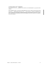
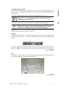
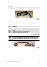
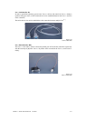
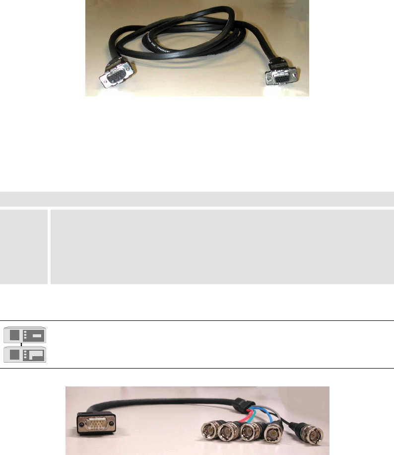
D15 – D15 Cable
Within a VISU
PLUS
– EOS setup the D15 – D15 cable is used to connect the analog output of EOS
with the RGB in connector of the analog input unit.
Figure 3-11
D15 – D15 cable
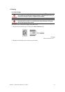
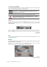
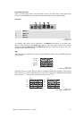
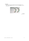
D15 – BNC Cable
The D15 – BNC cable is used to connect the output connector of the analog output unit with an
analog projection module or a CRT monitor. The table below shows the order of the output signals
as they are in the BNC connectors:
signal identification
Red red wire
Green green wire
Blue blue wire
Hsync undefined color, next to blue wire and not green wire
Vsync undefined color, next to Hsync and not blue wire
Table 3-1
color coding of BNC connectors
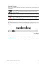
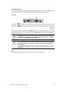
In a Visu
Plus
– Eos setup the processor board has to be synchronized with the
outgoing signal. Therefore the horizontal sync has to be connected to the HS in
connector of the processor board, the vertical sync has to be connected to the
VS in of the processor board, see section
3.2.7 Processor Board.
Figure 3-12
D15 – BNC cable