


R5976214 VisuPlus Video Insertion Unit June 2003
3-13
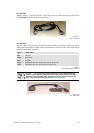
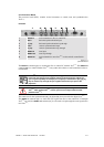
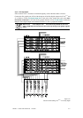
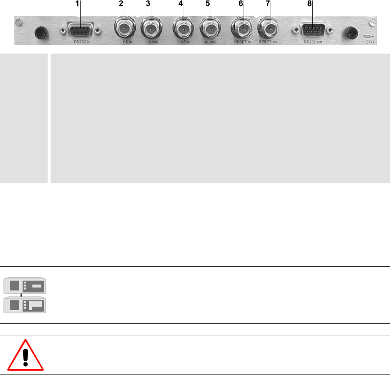
3.2.7 Processor Board
The processor board (CPU) contains several connectors to control, reset and synchronize the
V
ISU
PLUS
.
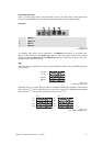
Connectors
1 RS232 in serial connection to EOS or control PC
2 HS in horizontal synchronization input
3 to proj. horizontal synchronization loop through
4 VS in vertical synchronization input
5 to proj. vertical synchronization loop through
6 RESET in reset input
7 RESET out reset loop through
8 RS232 out serial connection to next VISU
PLUS
or other serially controlled de-
vice
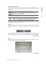
Figure 3-17
processor board
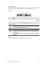
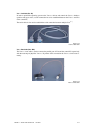
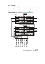
The RS232 in connector [1] is to connect the EOS or control PC with the VISU
PLUS
. The RS232 out
connector [8] is to connect another VISU
PLUS
or any other device that is as well controlled via the se-
rial interface.
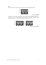
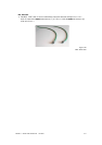
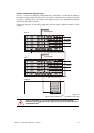
In Visu
Plus
– Eos setup the HS in [2] and VS in [4] connectors are to insert the
horizontal and vertical synchronization. When required (projectors without the
sync on green capability for example), the output sync connectors to proj. [3], [5]
may be used to loop through the sync signals towards the sync input of the
projectors.
Under no circumstances may the sync outputs be looped through to the next
Visu
Plus
. With multiple Visu
Plus
, use the syncs from an output channel of that
particular Visu
Plus
!
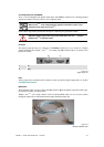
The connectors for the synchronization [2], [3], [4] and [5] are not used for the digital VISU
PLUS
.
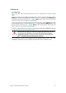
The
RESET in connector [6] is to insert the reset signal from EOS or the control PC. If multiple
V
ISU
PLUS
are used, the RESET out connector [7] is to be used to loop through the reset signal to the
next V
ISU
PLUS
.