


5-3
5
NI / 5E Custom Terminal Installation
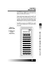
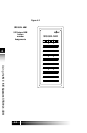
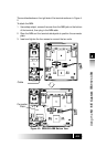
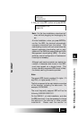
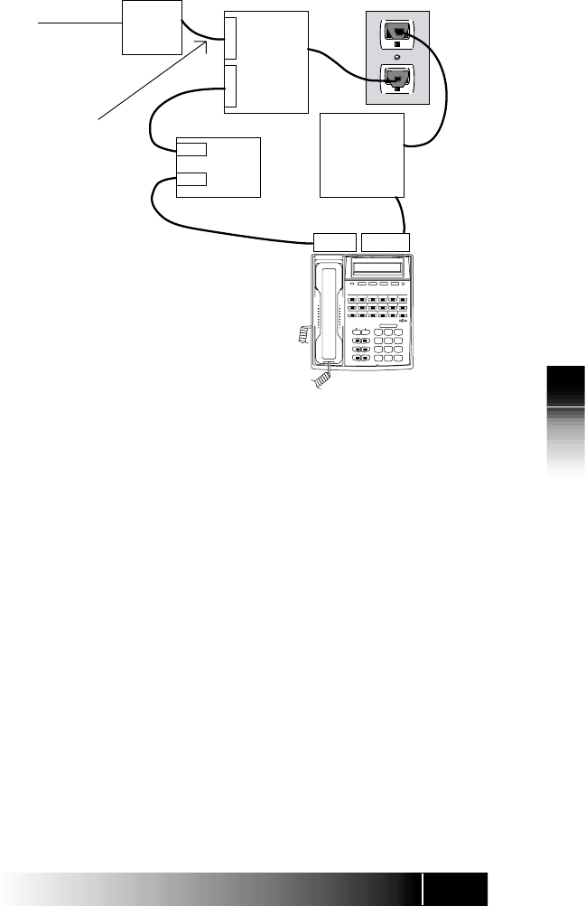
Figure 5-2: Power Connections
To Telco RJ-11
or
RJ-49
Power
Supply
L
I
N
E
N
T
1
NT1
Line
Term
AC
8 Wire
8 Wire
2 Wire or 4 Wire
(Low Wattage Supply)
FNC Power
Supply
Line
48 V DC
AC Adapter
AD-3645U
(optional)
(PS ON)
ISDN Set
(TA)
*
0 #
9
WXYZ
TUV
8
7
PQRS
GHI
4
JKL
5
6
MNO
DEF
3
ABC
2
1
SRS-9924
MENU
MSG
DROP CONF
TRAN REDIAL
HOLD SPKR
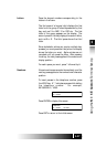
When you receive your terminal, plug the telephone
line from the wall into the LINE jack on the back of
the set. If the display shows a date and time, you
have power. If the display does not light up, you
may need assistance from your System
Administrator to complete the installation.
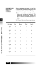
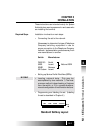
In order to assure proper operation, it is recom-
mended (not required) that you depress key pad
keys 1 and 6, while connecting the telephone to
the power source (either the wall jack or the AC
Adapter). Depress the keys for 10 seconds, until
the display goes blank. Then release the keys.
The set will go through its self test; you are ready
to complete installation when the default date, time
and the "?" appear on the display.
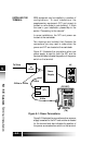
The Service Profile IDentifier (SPID) identifies your
set to the network. Your SPID may be supplied to
you by your service provider, or it may be supplied
automatically by the switch at installation. The
second option is called “Auto SPID”.
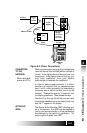
CONNECTING
TO THE
NETWORK
When using bulk
power and NT1s
SETTING-UP
SPIDS