


5-2
5
NI / 5E Custom Terminal Installation
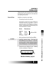
INSTALLING THE
TERMINAL
ISDN equipment may be installed in a number of
configurations. In most installations, the
supplementary equipment (NT1 and power) is
located in a wire closet in your building. If this is
the case in your installation, please skip to the
section “Connecting to the network”.
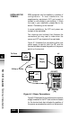
In some installations, the NT1 and power are
located at the user’s desk.
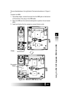
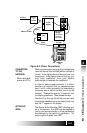
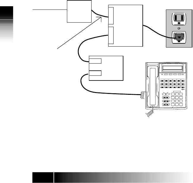
Two drawings are included that illustrate the
connections you may need to make when the
power and NT1 are located at the user’s desk.
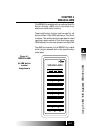
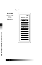
Figure 5-1 illustrates the connections when one
power supply is used for both the NT1 and the
terminal and also indicates the position of the power
switch on the terminal.
Figure 5-1: Power Connections
*
0 #
9
WXYZ
TUV
8
7
PQRS
GHI
4
JKL
5
6
MNO
DEF
3
ABC
2
1
SRS-9924
MENU
MSG
DROP CONF
TRAN REDIAL
HOLD SPKR
To Telco RJ-11
or
RJ-49
Power
Supply
L
I
N
E
N
T
1
NT1
Line
Term
AC
8 Wire
8 Wire
2 Wire or 4 Wire
(PS OFF)
ISDN Set
(TA)
Figure 5-2 illustrates the connections when a power
supply is needed for the NT1 and another is needed
for the terminal and also indicates the position of
the power source selection switch on the terminal.