


EXP1240 System Installation Guide Revision 06
© 2013 Uniden America Corp. PROPRIETARY AND CONFIDENTIAL Page 4 of 71
Table of Figures
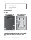
Figure 1 Base station front view ................................................................................................... 10
Figure 2 Base station rear view ..................................................................................................... 10
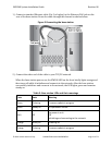
Figure 3 Connecting the base station ........................................................................................... 11
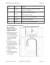
Figure 4: Base mounting dimensions ............................................................................................ 12
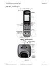
Figure 5: Handset front view ........................................................................................................ 13
Figure 6: Charger top view ............................................................................................................ 13
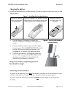
Figure 7: Installing the handset battery ........................................................................................ 14
Figure 8: Inserting the handset into the charger .......................................................................... 14
Figure 9: Home/Status screen .................................................................................................... 17
Figure 10: Management screen ................................................................................................... 18
Figure 11: Web Security screen .................................................................................................. 19
Figure 12: Country screen............................................................................................................ 20
Figure 13: Network screen ........................................................................................................... 20
Figure 14: Time Settings screen ................................................................................................. 21
Figure 15: Checking time settings updates ................................................................................... 22
Figure 16: Servers screen ............................................................................................................. 22
Figure 17: Add Extension screen ................................................................................................ 25
Figure 18: Extensions screen, no handsets registered ................................................................ 27
Figure 19: Extensions screen, one handset registered ............................................................... 27
Figure 20: Extensions screen, three handsets registered ........................................................... 28
Figure 21: Sample multi-cell system ............................................................................................. 30
Figure 22: Multi-cell screen (default values) .............................................................................. 32
Figure 23: Home/status screen (primary base enabled) ............................................................ 33
Figure 24: Multi-cell screen after configuration ......................................................................... 34
Figure 25: Base Station Group table, synchronizing (Multi-cell screen) ................................. 34
Figure 26: Base Station Group table, synchronization complete (Multi-cell screen) ............. 35
Figure 27: Base Station Group table, Level 1 complete (Multi-cell screen) ............................ 36
Figure 28: Base Station Group table, Level 2 added (Multi-cell screen) ................................. 37
Figure 29: Configuration screen ................................................................................................. 40