


MERLIN LEGEND Communications System Release 6.1
Network Reference
555-661-150
Issue 1
August 1998
Call-Handling Scenarios
Page 2-77Network Configuration Scenarios
2
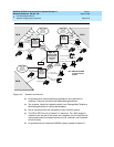
■ To reach System G, the routes for intersystem voice calls direct them from
Systems F and H via the hub, System E, where they are then sent to
System G over tandem tie facilities. FRLs for routes to System G are
slightly higher to avoid excessive call volume over the analog tandem tie
trunks.
NOTE:
In Release 6.1 and later, it is important to note that coverage to the
centralized VMS/AA from remote private network systems must be
limited to only one span. This means that a call may only pass
through one tandem trunk to the centralized VMS/AA on the hub
system.
■ Calls between extensions on Systems E, F, and H do display caller
information, according to display preference settings, at the destination
MLX display extensions.
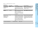
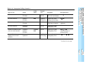
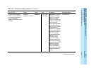
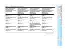
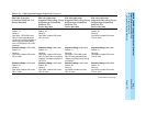
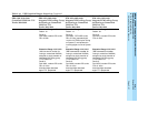
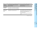
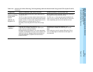
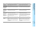
Table 2–20, page 2-82
shows how the system managers set up their local
systems for use of local PSTN facilities and non-local PSTN facilities. Remote
Access codes are not shown but are set up to be unique and unambiguous across
the private network. As you review the table, keep the following points in mind:
■ To avoid confusion and for future planning purposes, tandem trunks and
pools of tandem trunks are also numbered uniquely and unambiguously.
■ System H users do not make Interexchange calls. The system’s loop-start
line is assigned to the main pool, Pool 70.
CAUTION:
!
Unless networked systems are co-located, each system should have
at least one loop-start line connected to the PSTN. The line is
required to allow connection of a power-failure telephone to the
Power-Failure Transfer (PFT) jack on a module as a power outage
backup and for correct routing of emergency and other N11 (911, 411,
etc.) calls. To ensure that the correct services are reached, if the
loop-start line is used for emergency or other N11 calls, it should be
assigned to the main pool. In this case, inter-exchange (IXC) calls
determine the number of loop-starts required. Refer to
Feature
Reference
guide for details on the PFT feature.
■ The hub system, System E, can support only two tandem PRI trunks to
connect to Systems H and F, because it also requires a number of outside
facilities. It is using the maximum system capacity of 80 lines/trunks. Its
100D module is in the last circuit module position in the control unit and
uses only 20 lines of its 23-line capacity. There is no emergency loop-start
line connected to the system, therefore other power failure arrangements
should be made. Compare the limitations with those of Scenario 3, shown
in Figure 2–4 on page 2–58
.