


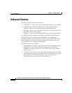

Chapter 1 Product Overview
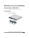
Hardware Features—WLSE 1130-19
1-6
Installation and Configuration Guide for the CiscoWorks Wireless LAN Solution Engine
78-16345-01
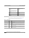
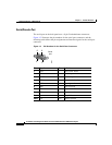
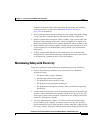
Serial/Console Port
The serial port on the back panel uses a 9-pin D-subminiature connectors.
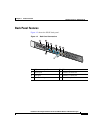
Figure 1-3 illustrates the pin numbers for the serial port connectors and the
following table defines the pin assignments and interface signals for the serial port
connector.
Figure 1-3 Pin Numbers for the Serial Port Connectors
Pin Signal I/O Definition
1 DCD I Data carrier detect
2 SIN I Serial input
3 SOUT O Serial output
4 DTR O Data terminal ready
5 GND N/A Signal ground
6 DSR I Data set ready
7 RTS O Request to send
8 CTS I Clear to send
9 RI I Ring indicator
Shell N/A N/A Chassis ground
Serial
port
1
5
6
9
58685