ALIGNMENT PROCEDURE AND PERFORMANCE TESTS
6-7
November 1999
Part No. 001-7780-500
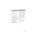
6.9 TRANSMITTER PERFORMANCE TESTS
6.9.1 POWER OUTPUT
Refer to Section 6.8.1 for information on test
channels. Proceed as follows:
1. Connect a wattmeter and dummy load tothe antenna
jack as described in Section 6.1.2.
2. Key the transmitter and highpower output should be
2.8-3.5 watts. Check channels on both ends of the
band.
3. Select the talk-around mode by pressing the Talk-
Around option switch. The talk-around mode is
indicated by in the display. Key the transmitter
and power output should be 2.5 watts or greater.
Check channels on both ends of the band.
4. Select the low power mode by pressing the High/
Low Power option switch. Low power is indicated
by “LOW” in the lower part of the display. Power
output should be 0.8-1.2 watt in the standard mode
and 0.7-1.2 watt in the talk-around mode.
6.9.2 TRANSMIT FREQUENCY
Monitor the transmit frequency with a communi-
cation monitor set to the channel frequency. At room
temperature, the frequency should be within ± 400 Hz.
This also checks the receive frequency.
6.9.3 TRANSMIT MODULATION
1. Select a channel not programmed for Call Guard
(CTCSS/DCS) squelch and monitor the transmit
signal with a communication monitor. Speak into
the microphone with a normal voice and modulation
should be approximately 3.4 kHz (wideband) or 1.4
kHz (narrow band).
2. Select a channel programmed for Call Guard
squelch and with no voice or other microphone
input signal, data deviation should be 1.0 kHz
(wideband) or 0.8 kHz (narrow band) ± 200 Hz.
3. Speak into the microphone with the channel
programmed for Call Guard squelch selected.
Maximum total audio and Call Guard deviation
should be 4.7 kHz (wideband) or 2.3 kHz (narrow
band).
6.9.4 TRANSMITTER CURRENT DRAIN
Maximum current drain in the transmit mode
should be as follows:
High Power, Standard Mode - 1.75 A
High Power, Talk-Around Mode - 2.0 A
Low Power, both modes - 1.3 A


