


ALIGNMENT PROCEDURE AND PERFORMANCE TESTS
6-4
November 1999
Part No. 001-7780-500
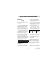
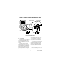
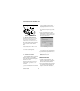
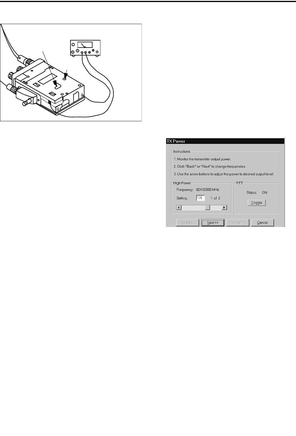
Figure 6-3 Connecting DC Power
6.1.6 REMOVING TRANSCEIVER COVER
NOTE: The transceiver cover needs to be removed
only if the frequency and squelch adjustments
described in Sections 6.2.1 and 6.6 need to be reset.
The frequency and squelch noise level adjust-
ments are made by manually resetting controls on the
RF board. To access these controls, proceed as
follows:
1. Remove the battery, belt clip, and back cover as
described in Section 1.11.
2. An external power supply must then be connected to
the transceiver as shown in Figure 6-3.
6.2 TRANSMIT FREQUENCY AND POWER
6.2.1 FREQUENCY ADJUSTMENT
Frequency adjustment should be performed with
the ambient temperature near the TCXO calibration
reference of 77° F (25° C). This ensures that the
frequency will be within tolerance at the temperature
extremes. Proceed as follows:
NOTE: The transmitter immediately keys when the
following function is selected. To turn the transmitter
on and off, click the “Toggle” button (see screen
which follows).
1. Connect a wattmeterand dummy load to the antenna
jack as shown in Figure 6-1.
2. Click the “Complete Tune” button to automatically
go from one adjustment to the next or click the
“Tune” button in the “Tx Power” box to perform
only this adjustment.
3. Monitor the transmit frequency with a communica-
tions monitor set to the frequency displayed on the
screen.
4. At room temperature, this frequency should be
within ± 400 Hz. If readjustment is required, remove
the cover as described in Section 6.1.6 and adjust
R73 (see Figure 6-3) for the correct frequency. This
also adjusts the receive frequency.
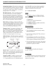
Transmit Power Adjustment Screen
6.2.2 POWER OUTPUT ADJUSTMENT
Set the high and low power output by clicking the
arrows or moving the button in the scroll bar. The rela-
tive power level is indicated by the number in the box.
Set the high and low power levels as follows:
High Power Level = 3.0 watts
Low Power Level =1.0watt
6.3 MODULATION BALANCE
1. If manually selecting each test, click the “Tune”
button in the “Modulation Balance” box. Otherwise,
this function is selected automatically when the
“Complete Tune” button is clicked.
2. View the transmit modulationwaveform on the CRT
of a communication monitor. If applicable, set the
monitor for de-emphasis off, high-pass filter off,
low-pass filter 3 kHz, and FM peak detection active.
7.5 VDC
Power Supply
(–) Neg
(+) Pos
R73
(Freq Adj)
R13
(Sq Lvl Adj)