


TRANSCEIVER PROGRAMMING
3-2
November 1999
Part No. 001-7780-500
Windows 95/98 - Select Start > Settings > Control
Panel and double click “Add/Remove Programs”.
Then click Install and Next. When SETUP.EXE is
automatically located on the floppy drive, click
Next, select the location for the start-up icon, and
enter the name you want to call the program.
4. Follow the instructions displayed by the setup
program. The default directory for the program is
\Program Files\PCTrunk. If you wish to use some
other directory, click Browse and select it or type the
name.
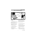
3.1.4 CONNECTING RPI TO COMPUTER AND
TRANSCEIVER
RPI Information
The RPI provides the required interface between
the computer and transceiver. It converts the RS-232
logic levels from the computer to the 5V logic levels
required by the transceiver microprocessor and vice
versa.
The current RPI available for programming trans-
ceivers of this type is Part No. 023-9800-000. Earlier
RPI’s, such as 023-9750-000 and 023-5810-000 can
also be used. However, the -9800- RPI is the only one
that has the speaker and microphone audio jacks
required to perform the alignment described in Section
6. In addition, it is the only RPI that can be used to
Flash program the transceiver to update the operating
software.
Cable Information
The cables from the RPI to the computer and
transceiver are not included with the RPI. The -9800-
RPI has a female DB9 connector for the computer
connection. Since most computer serial ports have a
male DB9 or DB25 connector, a male DB9 to female
DB9 or DB25 is usually required. This is a standard
cable available at most computer supply stores. A suit-
able cable is also listed in Table 1-1.
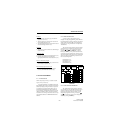
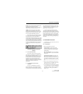
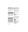
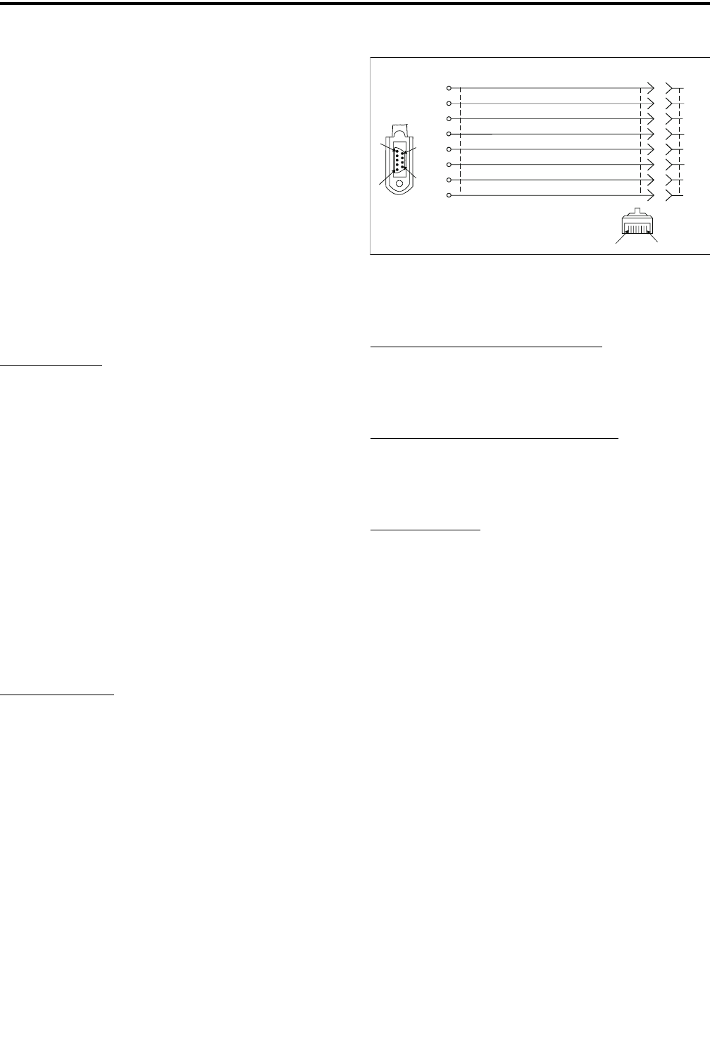
The cable from the RPI to the transceiver
connects from the RPI to the accessory connector of
the transceiver. A schematic diagram of this cable is
shown in Figure 3-2. The -122 version of this cable
can also be used because the extra wire connected to
pin 8 is not required with this radio.
Figure 3-2 RPI -Transceiver Cable Schematic
3.1.5 STARTING AND EXITING
To Start PCTrunk From Windows 3.1
In the Program Manager, open the PCTrunk
group window. Then double-click the PCTrunk icon.
To Start PCTrunk From Windows 95/98
Click the Start button and select the PCTrunk
group. Then double-click the PCTrunk icon.
To Exit PCTrunk:
SelectFile>ExitorpressALT+F4.
3.1.6
P
ROGRAMMING FILE TYPES
Programming data is stored in a disk file that can
be saved, read, copied, and deleted (see Section 3.3.1).
The file that is stored for each programming session
has the .DAT extension.
3.1.7 HELP FILES
To display help information on the current screen,
clickHelpinthemenubarorpressF1.
3.1.8 SCREEN TYPES
The following types of screens are displayed:
Radio-Wide - These screens program parameters that
are the same for all systems and channels. Separate
screens are displayed for General, Conventional,
SMARTNET/SmartZone, and Portable Options
parameters. Refer to Section 3.4 for more information
on these screens.
Modular
Connector
Orange
Black
Green
Yellow
Blue
White
Brown
Red
Pin A
Pin B
PROGRAMMING CABLE
Part No.597-2002-122/-123
RxD
Gnd
Mic Audio
Reset [1]
PTT
Vcc
Speaker
TxD
9
7
5
3
1
8
6
4
2
4
6
2
8
1
5
9
3
A
1
2
3
4
5
6
B
/Flash
[1] Pin 8 is connected on -123 cable only
To
RPI
To Radio
Accessory
Connector