


GENERAL INFORMATION
1-7
November 1999
Part No. 001-7780-500
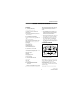
1.11.4 REMOVING RF UNIT
1. Remove the five screws attaching the shield to the
PC board.
2. Remove the two screws securing the RF power
module to the chassis. Then remove the four stand-
offs attaching the RF board to the chassis.
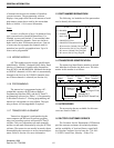
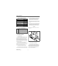
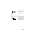
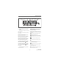
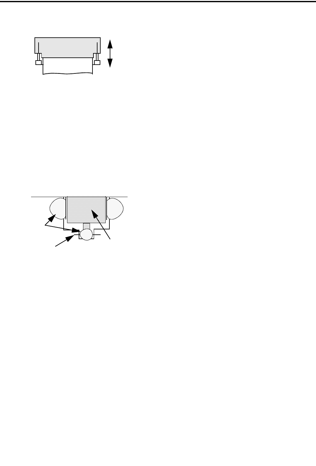
3. Unsolder the antenna connector from the PC board
by removing the solder at the locations shown in the
following illustration.
4. Remove the PC board by lifting it upward. The RF-
to-logic board connector under the IF board must
unplug, so some resistance may be encountered. Do
not pull on the IF or PLL board assemblies because
they can be easily damaged.
1.11.5 REMOVING LOGIC UNIT
1. Remove the top panel knobs. Then remove the
spanner nuts on the quick select and on-off/volume
switches. Remove the plastic top panel.
2. Unplug the flex cables from the front panel, acces-
sory connector, and PTT switch as described in
Section 1.11.3.
3. Unsolder the DC power flex circuit attached to the
logic unit near the accessory flex circuit connector.
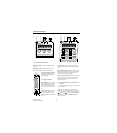
4. Remove the four screws attaching the logic unit to
the chassis.
5. Remove the logic unit by carefully lifting it
outward.The RF-to-logic boardconnector under the
IF board must unplug, so some resistance may be
encountered. There is a pry hole (indicated by an
arrow) on the lower left edge of the PC board.
LOCK
UNLOCK
WIRE IN
PC BD
ANTENNA
CONNECTOR
SOLDER